Modular flow cytometry system

Inactive Publication Date: 2006-08-31
PHI WILSON JANETTE TRANG
View PDF9 Cites 30 Cited by
  • Summary
  • Abstract
  • Description
  • Claims
  • Application Information

AI Technical Summary

Benefits of technology

[0042] In this embodiment, multiple sensor chips provide parallel, concurrent sample analysis using a single laser beam source. The laser light channel uses an optical fiber to carry the focused laser beam from the output end of the laser to the cytometer chip laser light channel. As the laser beam passes through each chip exciting various particl

Problems solved by technology

Due to the size and cost of existing laboratory or clinically-based flow cytometry systems, they are not effective for use in a field triage setting where mobility is critical.
Most current flow cytometry systems use the laser light source inefficiently.
If the target cell is an unknown, this number is insufficient to quickly identify a target cell

Method used


Image

  • Modular flow cytometry system
  • Modular flow cytometry system
  • Modular flow cytometry system

Examples


Embodiment Construction

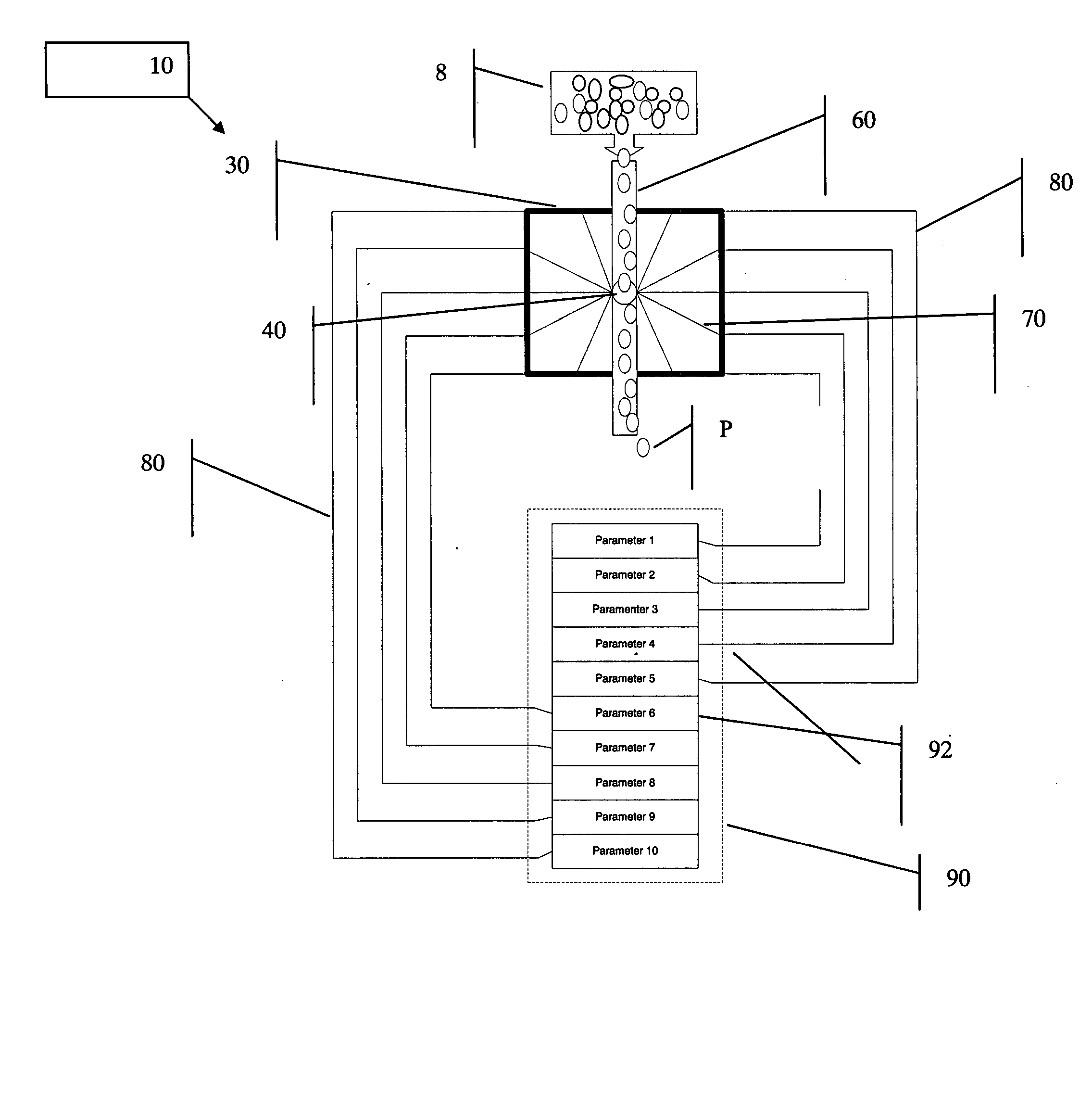
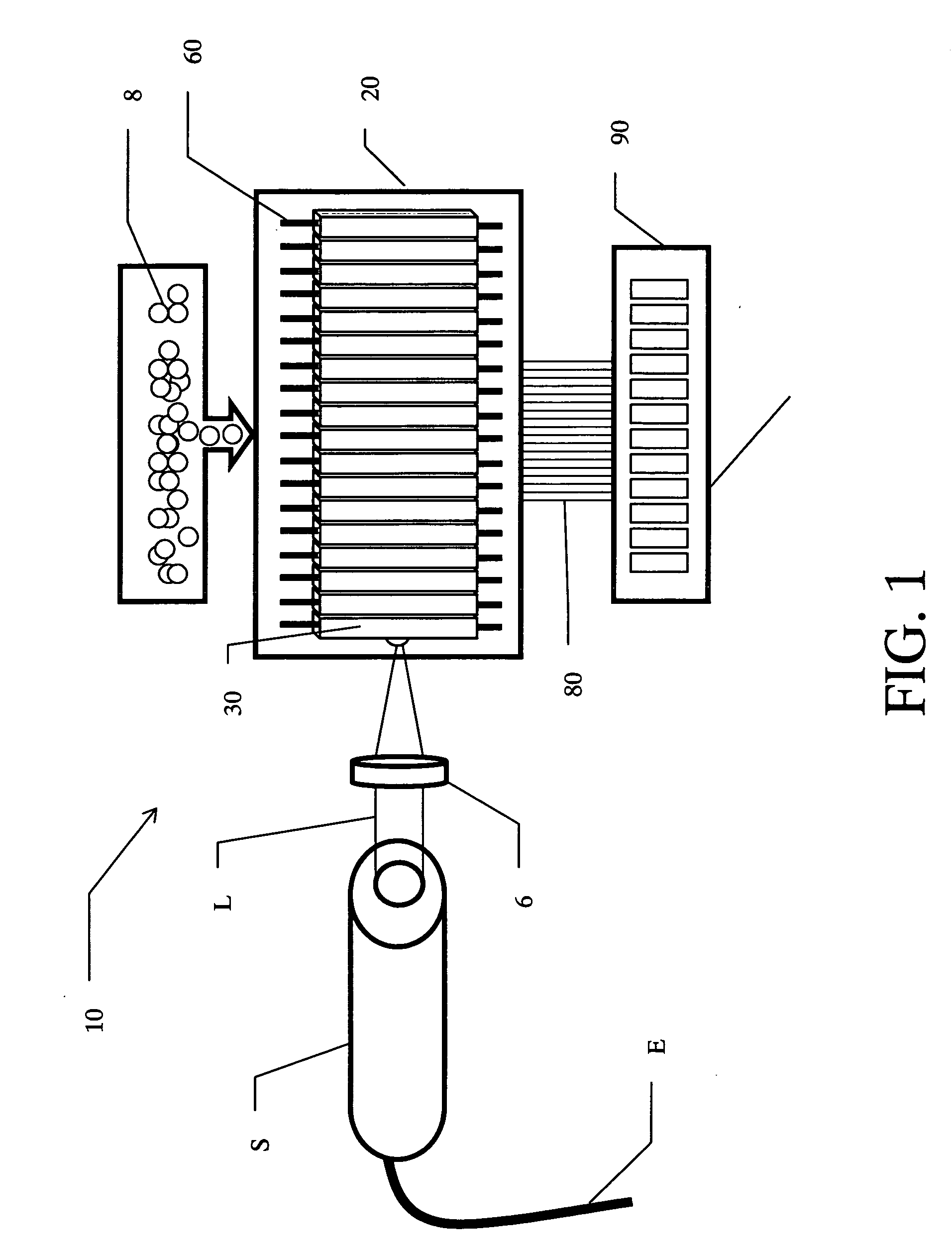
[0047] Referring to FIG. 1, a flow cytometry system 10 according to the present invention is comprised of a laser light source S connected to a power source E to generate a laser light beam L. The laser beam L passes through an optical focal lens 6. A sample solution storage reservoir 8 delivers samples to a flow stack 20 containing at least one flow chip 30. The flow chip 30 includes a centrally disposed flow chamber assembly 60. A signal transmission optical fiber 80 transmits scattered and fluoresced optical signals from the flow chip 30 to a photonic signal processing and analysis module 90.

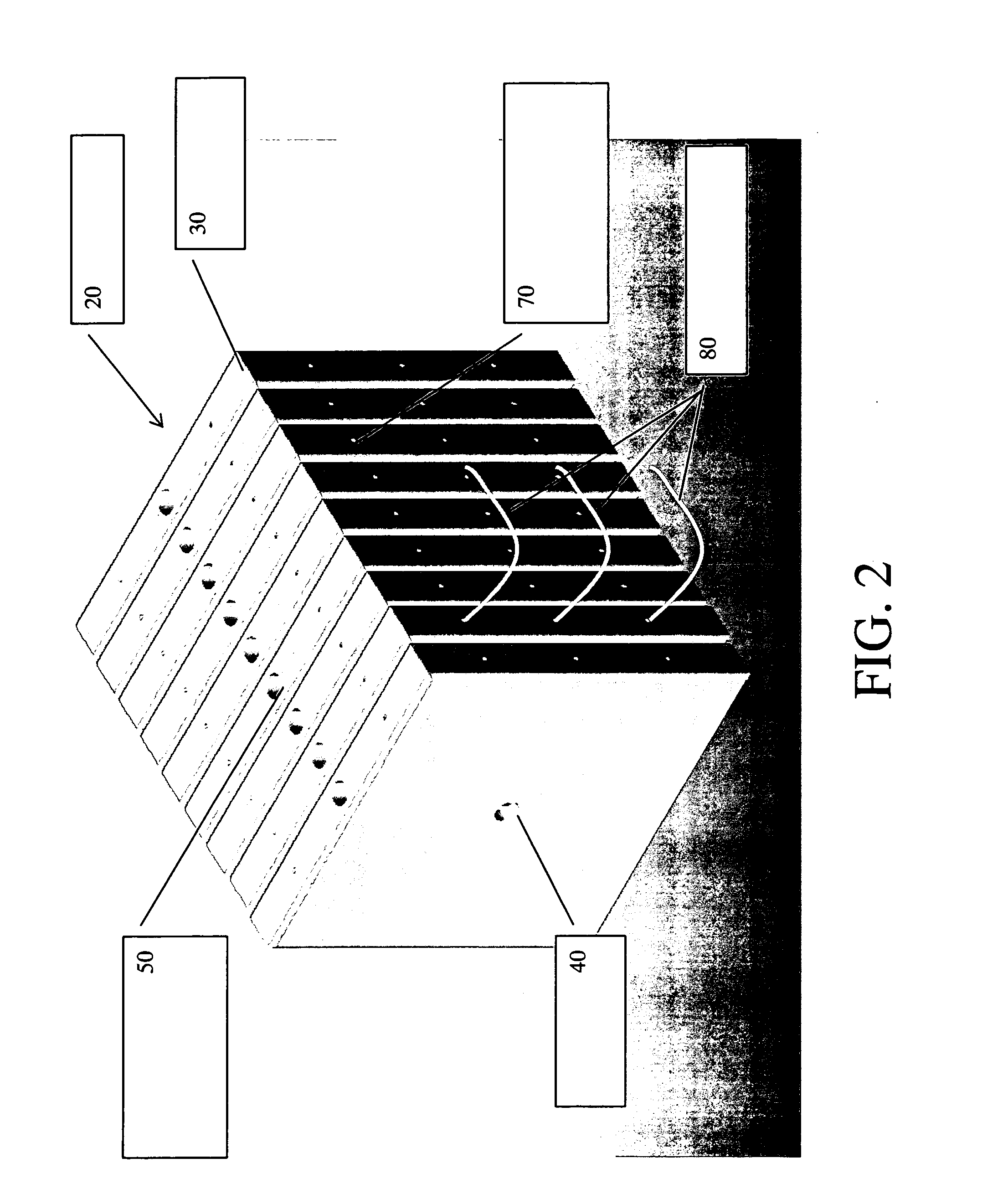
[0048] Referring to FIG. 2, the system 10 of the present invention includes a flow and detection module assembly, hereinafter, a flow stack 20. The flow stack 20 is comprised of one or more flow chips 30. A flow chip 30 includes a centrally-located laser light orifice 40 for receiving and transmitting the laser light beam. The flow chip 30 is laterally transected and bisected by a flow chamb...


PUM


Abstract

The present invention provides a novel flow cytometry system having high sample cell throughput with simultaneous single and multi-parameter development, extraction and analysis. The invention is comprised of one or more analytic modules or chips aggregated into a stack or chain creating a common laser light transmission channel while maintaining a separate fluid sample flow path within each chip. Each flow chip includes an array of optical fiber light receivers. Each chip also includes integrated waveguides to receive and channel scatter, reflected or fluoresced light of specific frequency and wavelength to the optical fiber receiver. One or more waveguides and optical fiber receivers may be incorporated within each flow chip. Each sensing optical fiber delivers its received light emission to an electro-optical system signal processing module for measuring, digitizing and identifying the light signal.

Description

CROSS-REFERENCE TO RELATED APPLICATIONS [0001] Priority is claimed to U.S. Provisional Application No. 60 / 645,787 filed Jan. 20, 2005, titled “MODULAR FLOW CYTOMETRY SYSTEM,” which is referred to and incorporated herein in its entirety by this reference.STATEMENT REGARDING FEDERALLY SPONSORED RESEARCH OR DEVELOPMENT [0002] Not Applicable SEQUENCE LISTING OR PROGRAM [0003] Not Applicable FIELD OF INVENTION [0004] This invention relates to a system for analyzing parameters of microparticles based upon flow cytometry techniques. More particularly, this invention relates to such a system having modular and scalable components for enhanced sensitivity and ability to detect one or more parameters simultaneously from one or more fluid samples using a single laser light source. BACKGROUND [0005] Flow cytometry involves the analysis of the fluorescence and light scatter properties of single particles, such as cells, nuclei and chromosomes, during their passage within a narrow, precisely defi...

Claims


Application Information

Patent Timeline
IPC IPC(8): G01N15/02G01N21/00
CPCG01N15/1459G01N15/1463G01N21/6428G01N21/645G01N2015/1477
Inventor PHI-WILSON, JANETTE TRANG
Owner PHI WILSON JANETTE TRANG
Why Eureka
Try Eureka