Capacity degredation in a lead acid battery method and apparatus

Inactive Publication Date: 2006-09-07
HONEYWELL INT INC
View PDF14 Cites 7 Cited by
  • Summary
  • Abstract
  • Description
  • Claims
  • Application Information

AI Technical Summary

Benefits of technology

[0006] In accordance with another embodiment of the invention, there is a battery defect detection apparatus comprising a control module comprising an analog-to-digital converter, a digital-to-analog converter, and an electronics control system. The apparatus also includes a power supply that supplies a current ramp to a battery, a sensor electrically c

Problems solved by technology

In addition, this approach can cause problems when

Method used


Image

  • Capacity degredation in a lead acid battery method and apparatus
  • Capacity degredation in a lead acid battery method and apparatus
  • Capacity degredation in a lead acid battery method and apparatus

Examples


Embodiment Construction

[0020] Reference will now be made in detail to the exemplary embodiments, examples of which are illustrated in the accompanying drawings. Wherever possible, the same reference numbers will be used throughout the drawings to refer to the same or like parts.

[0021] Embodiments described herein provide for detection of defects, which can lead to battery capacity degradation, without requiring battery discharge. Automated capacity determination algorithms can report the defect and / or predict capacity information of the battery to the user. Various embodiments described herein allow for automated and rapid defect detection in batteries, such as lead-acid batteries, without requiring additional testing of the battery. The detection technique can work in conjunction with existing automated capacity determination techniques.

[0022]FIGS. 1-7 disclose, generally, apparatus and methods for determining the degradation of a battery.

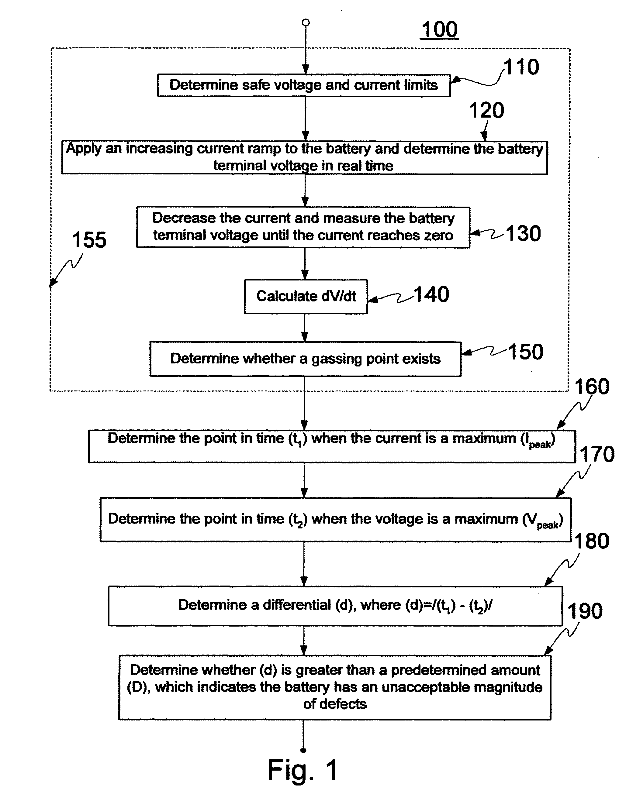
[0023]FIG. 1 depicts an exemplary flow chart of a method 100 to...


PUM


Abstract

In accordance with the invention, there is a battery defect detection method comprising applying a current ramp to a battery; determining a first time (t1) when a current of the battery reaches a maximum current (Ipeak), and determining a second time (t2) when a terminal voltage of the battery reaches a maximum voltage (Vpeak). The method also includes determining a differential (d), wherein (d)=/(t1)−(t2)/, and wherein (d) corresponds to a magnitude of defects in the battery.

Description

FIELD OF THE INVENTION [0001] The invention relates to methods and an apparatus for determining battery parameters such as battery capacity and battery analysis, and more particularly, to methods and an apparatus for determining capacity degradation in a battery. BACKGROUND OF THE INVENTION [0002] It is often desirable to determine whether a battery is functioning properly. Some systems test battery function by testing battery capacity through a full discharge under a specific load. A historical record of the measured capacities of the battery needs to be kept to determine battery degradation over time. In addition, this approach can cause problems when latent reaction defects are present in the battery. Latent reaction defects are generally understood to be a situation where the battery initially discharges normally, as defined by capacity, internal resistance, and polarization resistance, but after time and after battery conditions change, the discharge curve begins to drop more r...

Claims


Application Information

Patent Timeline
IPC IPC(8): H02J7/00
CPCG01R31/3627G01R31/3648G01R31/3668G01R31/3679G01R31/385G01R31/392G01R31/379
Inventor ATEHORTUA, HECTOR M.HOENIG, STEVENPALANISAMY, THIRUMALAI G.SINGH, HARMOHAN N.
Owner HONEYWELL INT INC
Why Eureka
Try Eureka