System and method for driving synchronous motor

a synchronous motor and control system technology, applied in the direction of motor/generator/converter stopper, electronic commutator, dynamo-electric converter control, etc., can solve the problem of system inability to determine the correct rotor position, the system cannot detect the sudden change of load torque, and the observation cycle of the terminal voltage is reduced, so as to improve the load follow-up performance. performance and the effect of reducing the observation cycl

Active Publication Date: 2007-05-31
HITACHI POWER SEMICON DEVICE
View PDF1 Cites 68 Cited by
  • Summary
  • Abstract
  • Description
  • Claims
  • Application Information

AI Technical Summary

Benefits of technology

[0010] It is an object of the invention to provide a driving system of a permanent magnet synchronous motor that reduces an observation cycle of a terminal voltage of the motor and can withstand abrupt load fluctuation.
[0011] A motor driving apparatus according to the invention reduces an observation cycle of a terminal volt

Problems solved by technology

As the cycle for acquiring the information of the rotor position gets thus elongated and an abrupt load torque change cannot be detected with the result of the stop of the motor.
When the induced voltage becomes greater than the induced voltage, an error occurs in the calculation of the rotor position.
This sys

Method used


Image

  • System and method for driving synchronous motor
  • System and method for driving synchronous motor
  • System and method for driving synchronous motor

Examples


embodiment 1

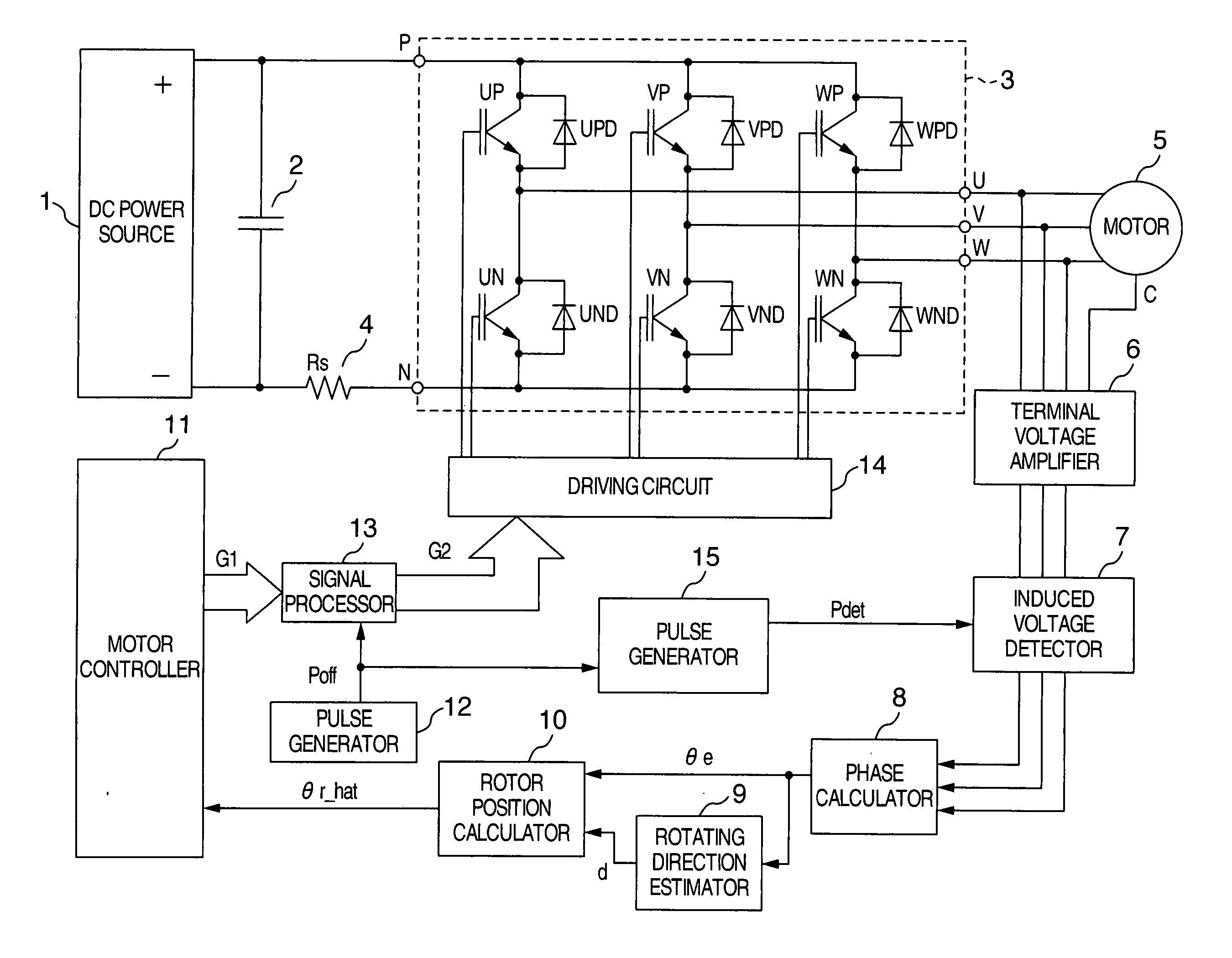
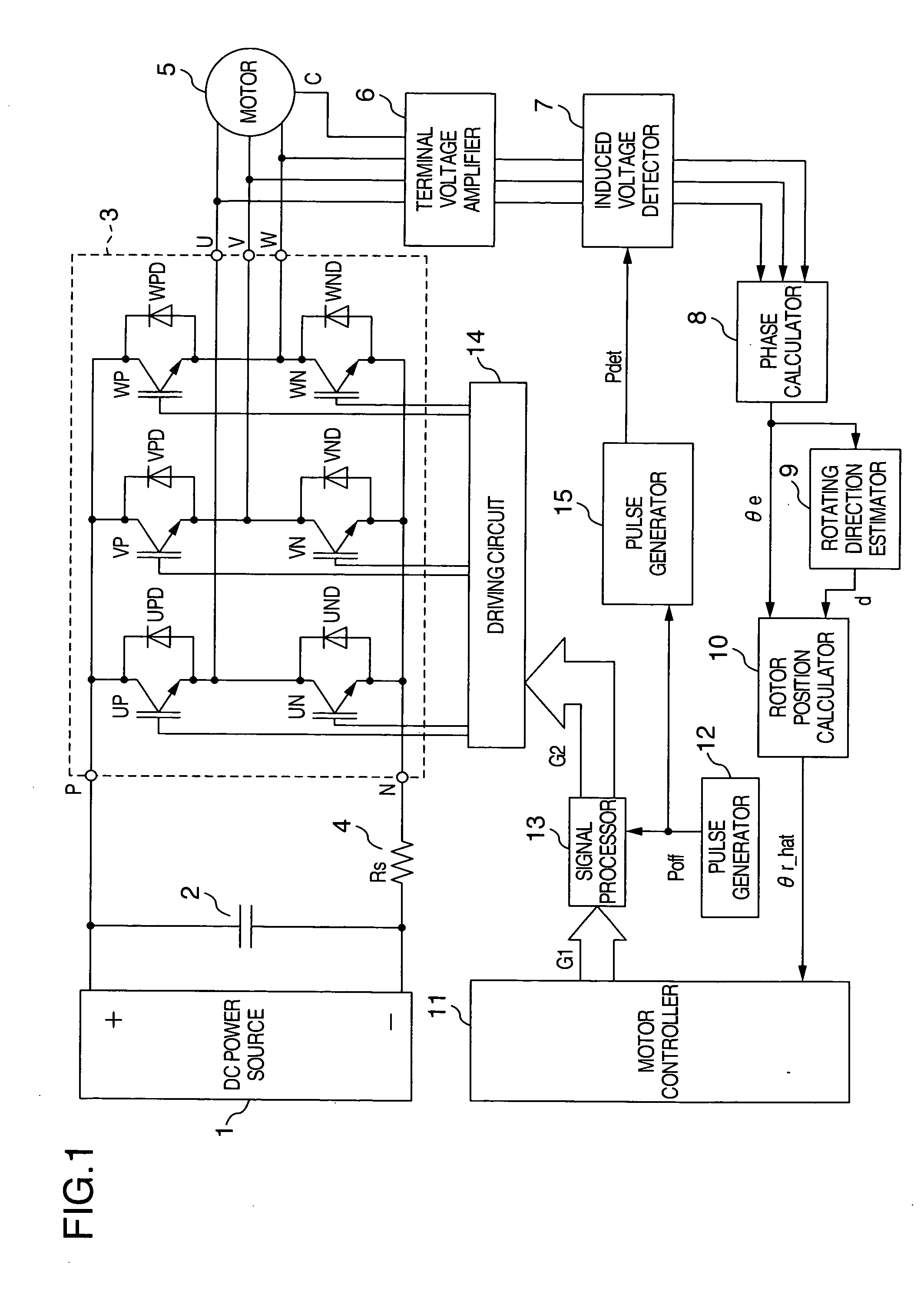
[0033]FIG. 1 shows a structural view of this embodiment. A capacitor 2 for smoothing a DC voltage is connected between a positive terminal and a negative terminal of a DC power source 1. The positive terminal of the capacitor 2 is connected with a DC positive terminal P of inverter 3. A DC negative terminal N of an inverter 3 is connected to the negative terminal of the capacitor 2 through a shunt resistor 4. AC terminals U, V and W of a synchronous motor 5 such as a permanent magnet synchronous motor as a control object are connected to AC output terminals of the inverter 3. The synchronous motor 5 is driven by three-phase AC power supplied by the inverter 3.

[0034] A terminal voltage amplifier 6 is connected to the AC terminals (U, V, W) of the synchronous motor 5 and to a neutral terminal C of a stator winding. The terminal voltage amplifier 6 multiplies the voltage between the AC terminal (U, V, W) and the neutral terminal C by a predetermined gain and outputs the product as a t...

embodiment 2

[0066] In this embodiment, the wait time Tw is set by measuring the current decrease in the free wheel mode. FIG. 13 shows a structural view of this embodiment. Only different portions of the construction will be explained in comparison with FIG. 1 showing the first embodiment. A voltage across both ends of the shut resistor 4 is converted to a current signal IDC by the current detector 16. The current signal IDC is connected to the pulse generator 15.

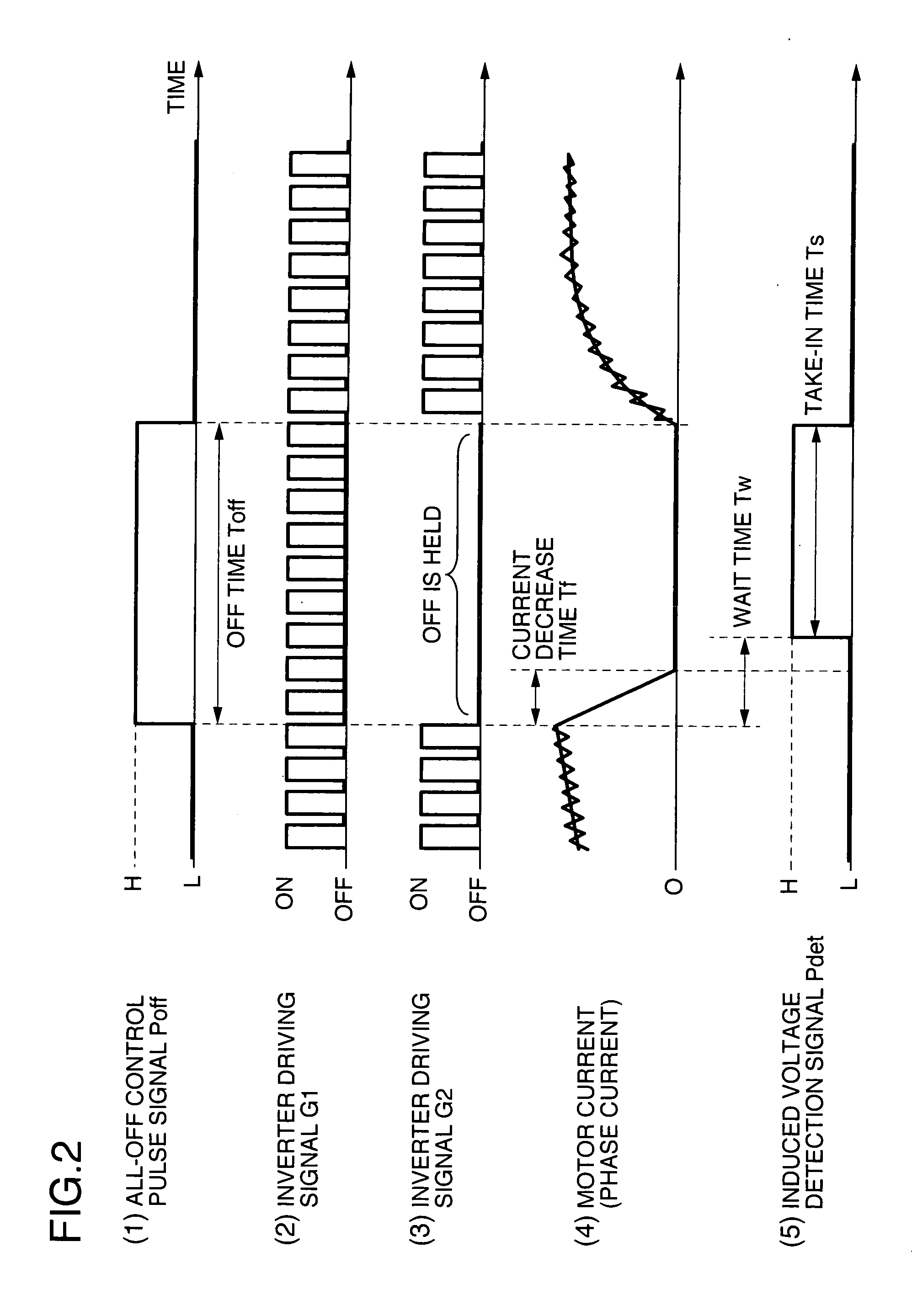
[0067] The current path in the free wheel mode contains the shunt resistor 4 as can be seen from FIG. 10. Therefore, when the voltage across both ends of the shunt resistor 4 is measured, the timing at which the current in the free wheel mode becomes zero can be acquired. The pulse generator 15 shown in FIG. 13 changes the induced voltage detection signal Pdet to the H level simultaneously with the time at which the current signal IDC becomes zero after the change of the all-OFF control pulse signal Poff to the H level or with a prede...

embodiment 3

[0069] In the motor driving apparatuses of the first and second embodiments shown in FIGS. 1 and 13, the value of the back electromotive force KE of the motor during driving is measured in this embodiment and control is executed while the set value is corrected. The explanation will be hereinafter given.

[0070] To estimate the rotor position, the induced voltage of the synchronous motor 5 during driving is measured in this embodiment. Because the induced voltages of two or more phases are detected, the peak value of the induced voltage can be determined from the measured voltage unless the output of the induced voltage detector 7 gets into saturation.

[0071] When the terminal voltage amplifier 6 employs the phase voltage detection system shown in FIG. 4A, the peak value of the induced voltage in the phase voltage can be determined by using α and β obtained from equation (1).

|E|=√{square root over (α2+β2)}=g·KEωm  (11)

[0072] It is possible to consider the angular frequency ω1 of the ...


PUM


Abstract

A driving apparatus of a synchronous motor fixes all the switching devices of an inverter at OFF in accordance with a value of an all-OFF control pulse signal outputted by a pulse generator. A motor current keeps flowing through free wheel diodes for a predetermined period even after all the switching devices shift to the OFF state. Therefore, pulse generator changes an induced voltage detection signal to an H (high) level after the passage of the time in which a motor current drops down to zero. A terminal voltage of the motor is taken in to acquire an induced voltage and a rotor position is estimated.

Description

BACKGROUND OF THE INVENTION [0001] This invention relates to a control system of a synchronous motor. More particularly, the invention relates to a driving system of a synchronous motor capable of driving a permanent magnet synchronous motor without using a sensor for detecting a rotor position. [0002] Among position sensor-less control technologies for controlling a permanent magnet synchronous motor without using a sensor for detecting a rotor position, a controlling method of a motor by measuring a terminal voltage of the motor and controlling the motor on the basis of this voltage has been primarily used for driving apparatuses of motors having a relatively low voltage. This method will be hereinafter called a “terminal voltage detection system”. [0003] Next, the terminal voltage detection system will be explained. Japanese Patent No. 3613063 (paragraphs (0037) to (0051)) describes a terminal voltage detection system in “120-degree power feed driving” as a simple driving method ...

Claims


Application Information

Patent Timeline
IPC IPC(8): H02P6/00H02P6/06H02P6/18H02P6/08H02P6/182
CPCH02P6/185H02P25/023H02P25/03
Inventor SAKAMOTO, KIYOSHIENDO, TSUNEHIROSHIRAHAMA, HIDEFUMIAJIMA, YOSHIAKI
Owner HITACHI POWER SEMICON DEVICE
Why Eureka
Try Eureka