

Exposure method and apparatus
a technology of exposure method and apparatus, applied in the field of exposure apparatus, can solve the problems of spherical aberration, low refractive index of the medium, and unstable temperature ris
- Summary
- Abstract
- Description
- Claims
- Application Information
AI Technical Summary
Benefits of technology
Problems solved by technology
Method used
Image

Examples
first embodiment
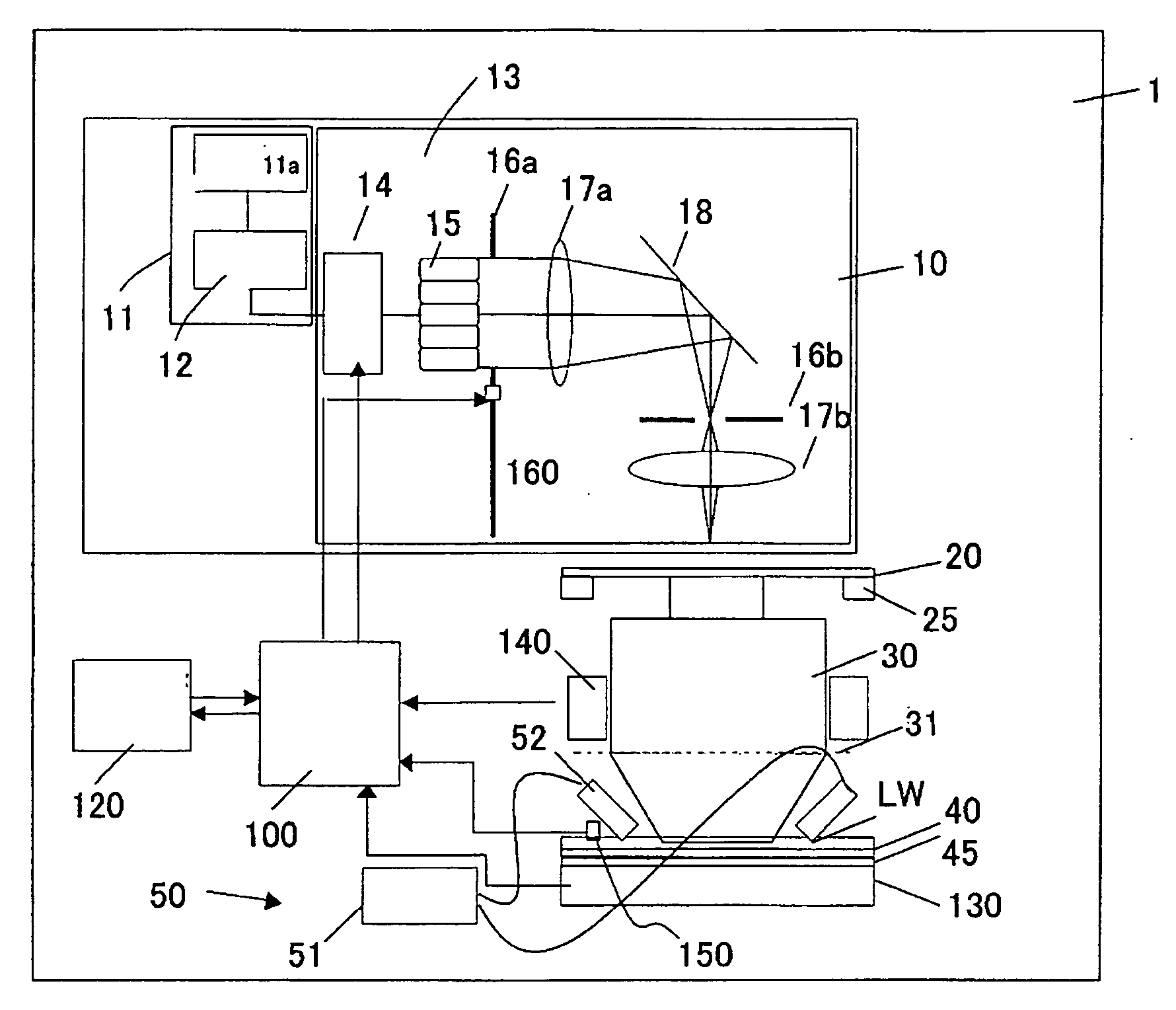
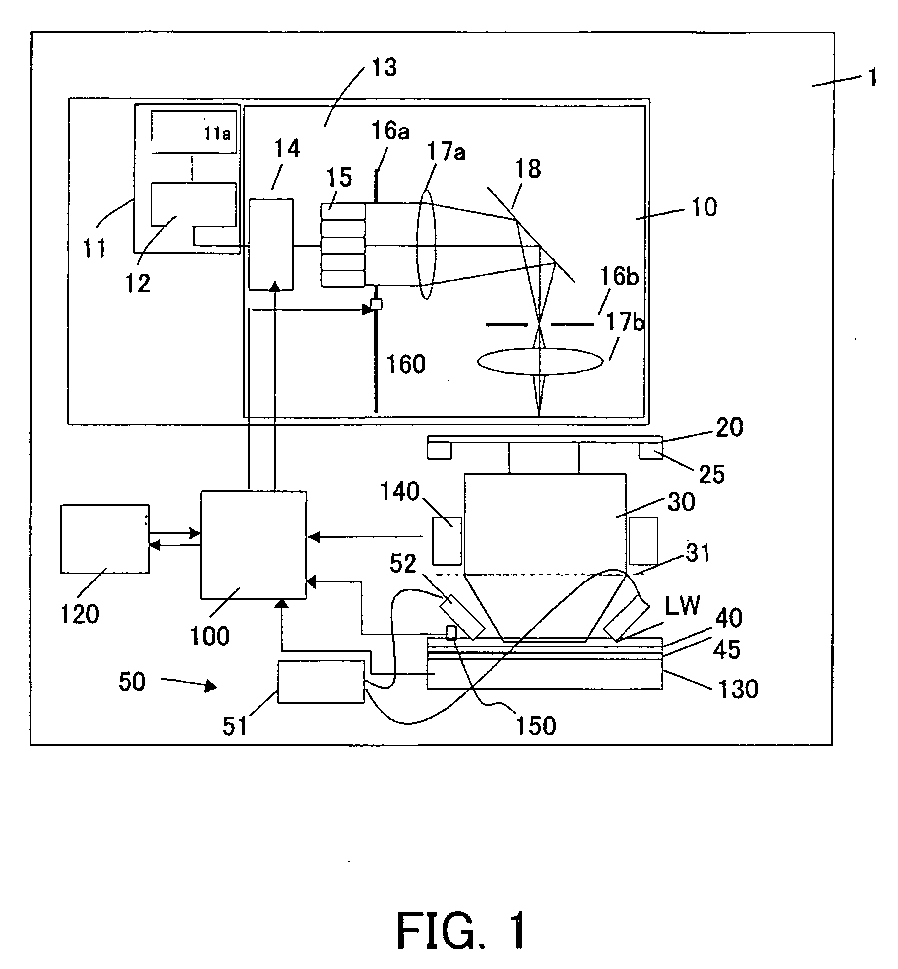
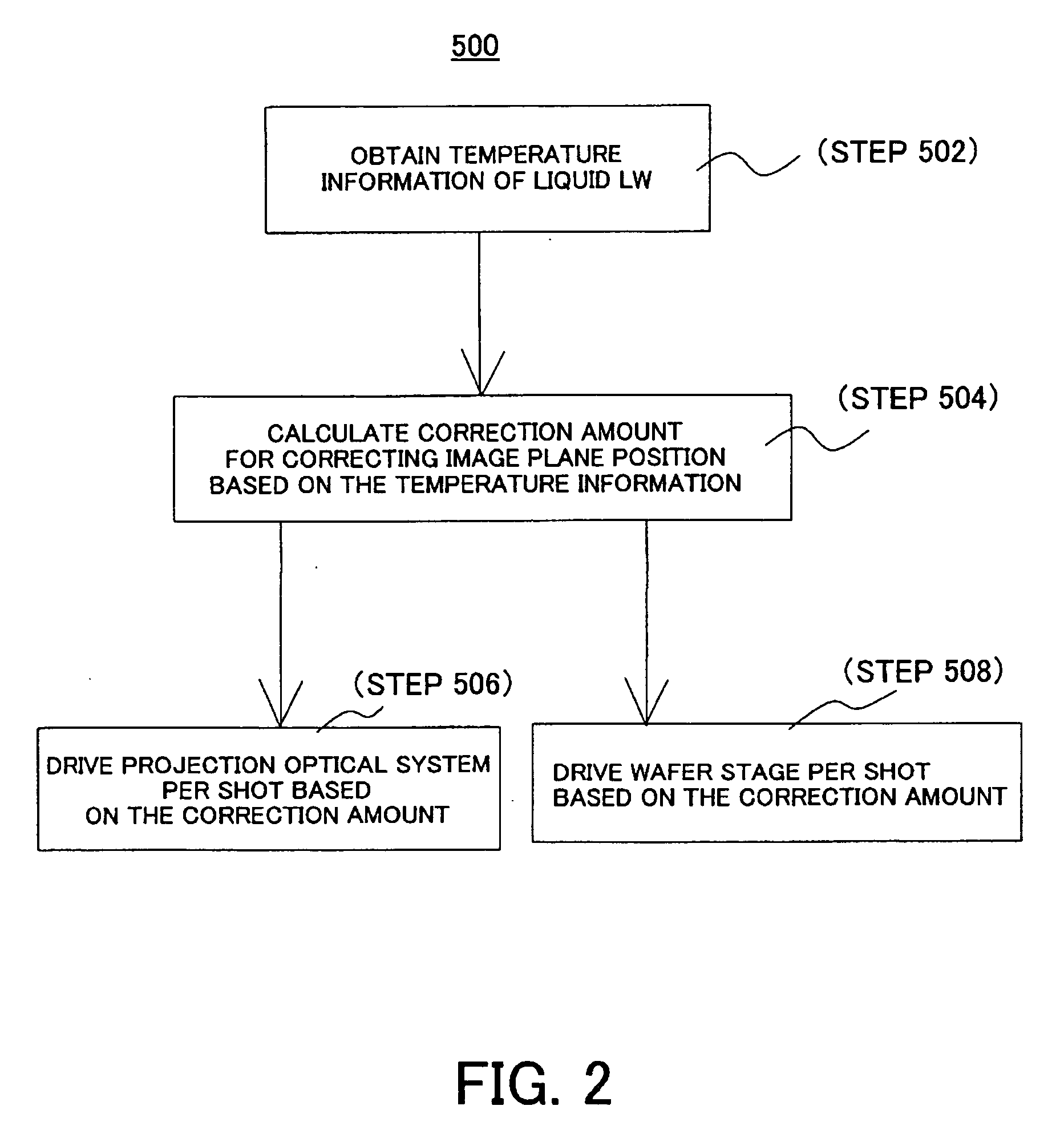
[0060] The light that passes the reticle 20 and reflects a reticle pattern is imaged on the wafer 40 via the projection optical system 30 and the liquid LW. The liquid LW's temperature information or aberration information (collectively referred to as “temperature information” in this specification unless otherwise specified) is obtained (step 502). The temperature information covers both temperatures above an exposure area and a periphery of the exposure area (or a non-exposure area) on the wafer. The temperature information above the exposure area is important. This embodiment obtains the temperature of the liquid LW using the detector 150.
[0061] By using a constant that indicates a refractive index change to a temperature change, the temperature distribution is multiplied by the constant and converted into the refractive index, or aberration or a focus error. The “focus error,” means a change of an imaging position of a reticle pattern, or a change of a focal position of an imag...
second embodiment
[0075] Referring now to FIG. 3, an exposure method 500A will be described. FIG. 3 is a flowchart of the exposure method 500A.
[0076] The light that passes the reticle 20 and reflects a reticle pattern is imaged on the wafer 40 via the projection optical system 30 and the liquid LW. The liquid LW's temperature information is obtained (step 502). Similar to the first embodiment, the temperature information may be obtained by measuring the temperature distribution or the focus position change. The temperature information may be obtained previously or during exposure. This embodiment obtains the temperature of the liquid LW using the detector 150. The obtained temperature information is fed to the controller 100.
[0077] The dose of the non-exposure light as a correction amount is determined based on the temperature information (step 504). The correction amount is calculated by the controller 100. The temperature information is obtained every shot. When there is no temperature informatio...
third embodiment
[0092] Referring now to FIG. 4, an exposure method 500B will be described. FIG. 4 is a flowchart of the exposure method 500B.
[0093] The light that passes the reticle 20 and reflects a reticle pattern is imaged on the wafer 40 via the projection optical system 30 and the liquid LW. The liquid LW's temperature information is obtained (step 502). Similar to the first embodiment, the temperature information may be obtained by measuring the temperature distribution or the focus change. The temperature information may be obtained previously or during exposure. This embodiment obtains the temperature of the liquid LW using the detector 150. The obtained temperature information is fed to the controller 100.
[0094] A correction amount for correcting the focus position is determined based on the temperature information (step 504). The correction amount is calculated by the controller 100. The temperature information is obtained every shot.
[0095] Next, the speed of the wafer stage 45 is chan...
PUM
 Abstract
Description
Claims
Application Information