Illumination optical system and exposure apparatus having the same

an optical system and exposure apparatus technology, applied in the field of illumination optical systems, can solve the problems of deterioration of the internal transmittance of optical materials, deterioration of the light intensity of optical materials, and decrease the throughput of exposure apparatus, so as to achieve high-quality exposure, reduce throughput, and expand the zooming range

Inactive Publication Date: 2009-03-03
CANON KK
View PDF18 Cites 2 Cited by
  • Summary
  • Abstract
  • Description
  • Claims
  • Application Information

AI Technical Summary

Benefits of technology

[0009]Accordingly, it is an exemplary object of the present invention to provide an illumination optical system and an exposure apparatus having the same that prevent the reduced throughput due to the deteriorated light intensity, expand the zooming range, and provide the high-quality exposure.

Problems solved by technology

The high light energy density at the re-condensing position causes deteriorations in the internal transmittance of an optical material that composes the lens, and anti-reflection coatings applied onto the lens surfaces.
In other words, the re-condensing position located near the lens would damage the lens, deteriorate its light intensity, and decrease the throughput of the exposure apparatus.
Therefore, the illumination optical system may not possibly obtain the optimized σ or achieve the desired resolution for some circuit patterns.

Method used


Image

  • Illumination optical system and exposure apparatus having the same
  • Illumination optical system and exposure apparatus having the same
  • Illumination optical system and exposure apparatus having the same

Examples


Embodiment Construction

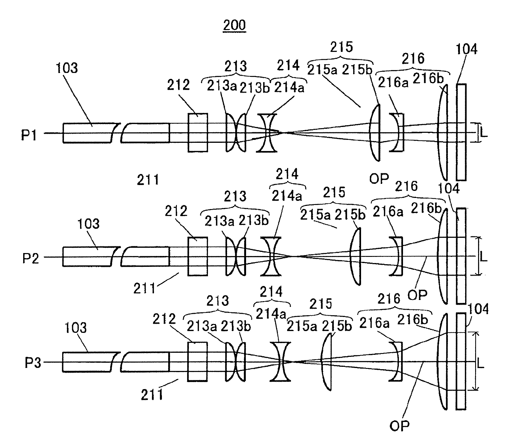
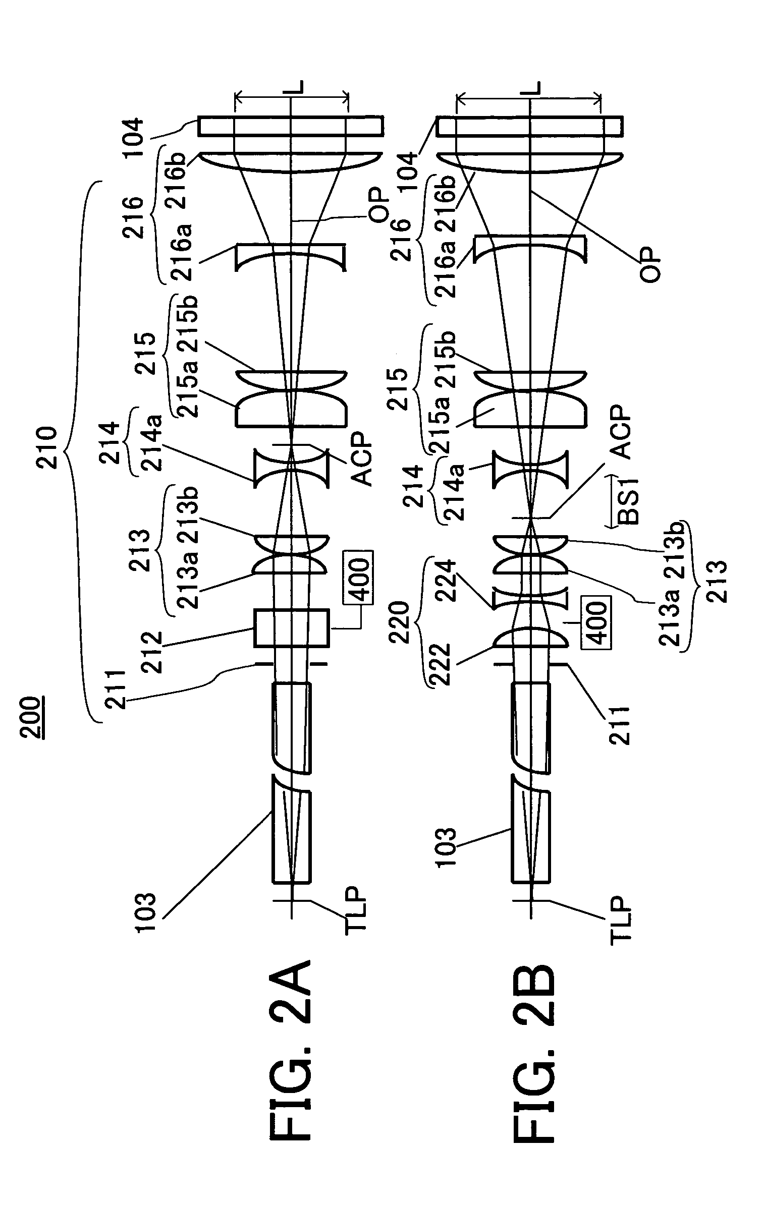
[0051]A σ variable optical system of an illumination optical system of the present invention should meet three conditions on an exit side of the σ variable optical system, i.e., a zooming operation that changes an irradiated area, an immobility at the back focus position, and a telecentricity of the exit light, in order to provide an illumination optical system and an exposure apparatus having the same for preventing the lowered throughput due to the light intensity deterioration, and for expanding a zooming range to provide the high-quality exposure. In general, at least three movable units are needed to satisfy these three conditions.

[0052]However, if a second optical system, which will be described later, is introduced, only two movable units enables the immobility at the back focus position of a first optical system and the telecentric of exit light, which will be described later, to fall within a substantially permissible range, providing the σ variable optical system that has ...


PUM

PropertyMeasurementUnit
diameteraaaaaaaaaa
lengthaaaaaaaaaa
diameteraaaaaaaaaa

Abstract

An illumination optical system for illuminating an object surface using light from a light source, the illumination optical system includes, a first optical system that includes a movable unit that is movable along an optical axis, said first optical system guiding the light to the object surface and varying an irradiation area on a certain plane, and a second optical system that can be located on and removed from an optical path of said first optical system, the second optical system varies, when located on the optical path of said first optical system, the irradiation area on the certain plane in cooperation with said first optical system, while maintaining a shape of a light intensity distribution on the certain plane, relative to the irradiation area irradiated only by said first optical system.

Description

BACKGROUND OF THE INVENTION[0001]The present invention relates generally to an illumination optical system, and more particularly to an illumination optical system for illuminating a reticle (or a mask) which forms a pattern, in an exposure apparatus used in a photolithography process for fabricating semiconductor devices, liquid crystal display devices, image pick-up devices (CCD, and the like), thin-film magnetic heads, and the like.[0002]The photolithography technology for manufacturing fine semiconductor devices, such as LSIs and very large scale integrations, has conventionally employed a reduction projection exposure apparatus that uses a projection optical system to project and transfer a circuit pattern formed on a reticle onto a wafer, etc. As the recent improved packaging density of the semiconductor devices requires finer patterns, the exposure apparatus needs to improve the resolution (to correspond to the fine processing).[0003]The improved resolution of the exposure ap...

Claims


Application Information

Patent Timeline
Patent Type & Authority Patents(United States)
IPC IPC(8): G03B27/54G02B19/00G02B15/04G02B15/10G02B15/167G03F7/20H01L21/027
CPCG03F7/70183
Inventor ORINO, KANJO
Owner CANON KK
Why Eureka
Try Eureka