
Gain and signal level adjustments of cascaded optical amplifiers

Inactive Publication Date: 2006-09-07
FUJITSU LTD
View PDF26 Cites 19 Cited by
  • Summary
  • Abstract
  • Description
  • Claims
  • Application Information

AI Technical Summary

Benefits of technology

[0013] Accordingly, it is an object of the present invention to provide an optical amplification device and method which does not require a high-power pumping light source.
[0014] It is an additional object of the present invention to provide an optical amplification device and method which can maintain the wavelength characteristic of gain constant and can obtain a wide input dynamic range, while requiring a relatively low power pump light.
[0022] Objects of the present invention are also achieved by providing an apparatus including a first optical amplifier which amplifies a light with a gain of the first optical amplifier. A first gain controller controls the gain of the first optical amplifier to be constant at a target gain. A second optical amplifier receives the light amplified by the first optical amplifier, and amplifies the received light with a gain of the second optical amplifier. A gain deviation detector detects a deviation in gain of the first optical amplifier from the target gain. A gain adjustor adjusts the gain of the second optical amplifier to compensate for the detected deviation in gain of the first optical amplifier. A level controller can control a level of the light amplified by the first optical amplifier before being amplified by the second optical amplifier to be at a target level, wherein the level controller adjusts the target level to compensate for a detected deviation in gain of the first optical amplifier by the gain deviation detector.

Problems solved by technology

Accordingly, there arises a problem such that when the power of signal light to be supplied to the first optical amplifier is increased, the power of pump light must be increased by the corresponding amount to increase the output power of the first optical amplifier to provide the required gain.

Method used


Image

  • Gain and signal level adjustments of cascaded optical amplifiers
  • Gain and signal level adjustments of cascaded optical amplifiers
  • Gain and signal level adjustments of cascaded optical amplifiers

Examples


Embodiment Construction

[0052] Reference will now be made in detail to the present preferred embodiments of the present invention, examples of which are illustrated in the accompanying drawings, wherein like reference numerals refer to like elements throughout.

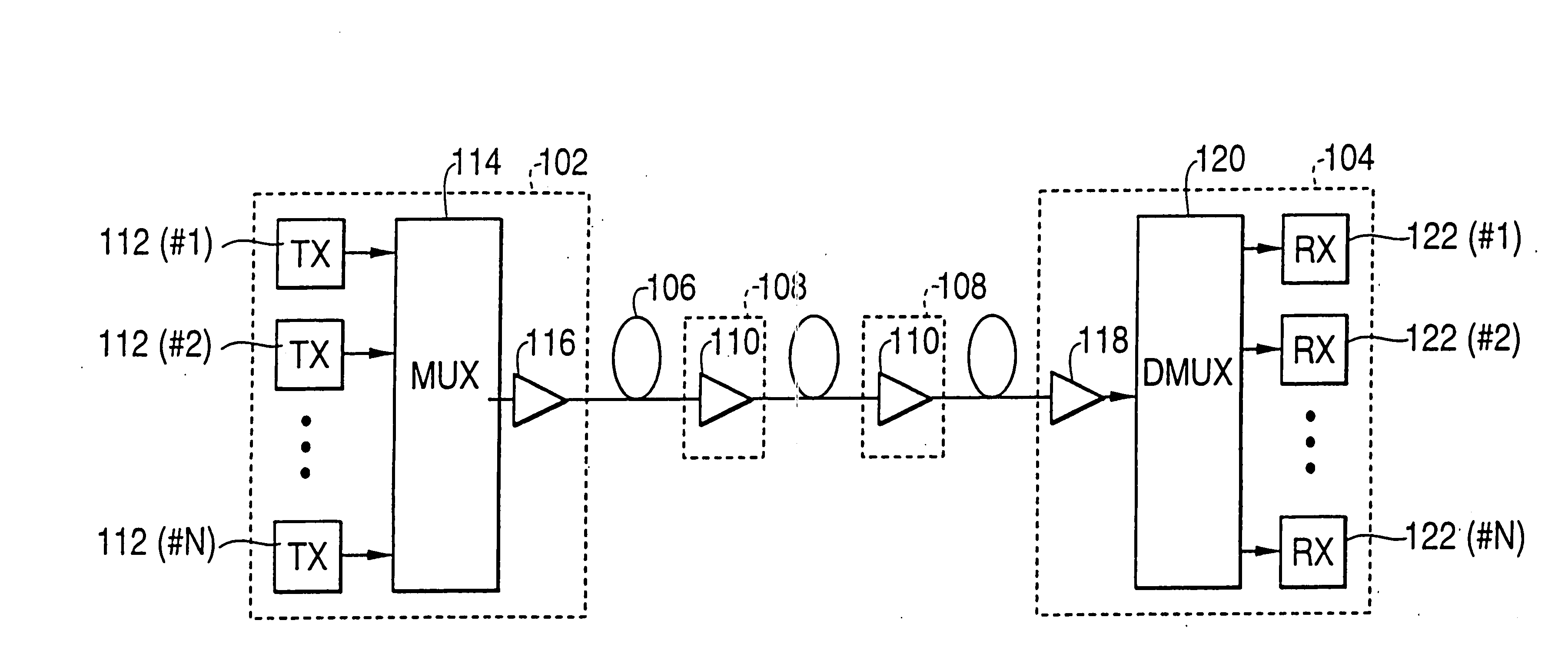
[0053]FIG. 1 is a diagram illustrating an optical fiber communication system, according to an embodiment of the present invention. Referring now to FIG. 1, the system includes a first terminal station 102, a second terminal station 104, an optical fiber transmission line 106 connecting terminal stations 102 and 104, and a plurality of optical repeaters 108 arranged along optical fiber transmission line 106. Each optical repeater 108 includes an optical amplifier 110 optically connected to optical fiber transmission line 106. Although FIG. 1 shows two optical repeaters 108, more than two optical repeaters can be used, depending on the system design parameters. Further, in some systems, a single optical repeater may be used.

[0054] First terminal stat...


PUM


Abstract

An optical amplification device which includes first and second optical amplifiers, and a controller. The first optical amplifier receives a light and amplifies the received light. The second optical amplifier receives the light amplified by the first optical amplifier, and amplifies the received light. When a level of the light received by the first optical amplifier changes by Δ, the controller controls a level of the light received by the second optical amplifier to change by approximately −Δ. In various embodiments, the controller causes the sum of the gains of the first and second optical amplifiers to be constant. In other embodiments, the optical amplification device includes first and second optical amplifier and a gain adjustor. The gain adjustor detects a deviation in gain of the first optical amplifier from a target gain, and adjusts the gain of the second optical amplifier to compensate for the detected deviation.

Description

CROSS-REFERENCE TO RELATED APPLICATION [0001] This application is based on, and claims priority to, Japanese application number 10-70251, filed on Mar. 19, 1998, in Japan, and which is incorporated herein by reference. [0002] This application is also based on, and claims priority to, Japanese application number 10-258114, filed on Sep. 11, 1998, in Japan, and which is incorporated herein by reference. BACKGROUND OF THE INVENTION [0003] 1. Field of the Invention [0004] The present invention relates to cascaded optical amplifiers and, more particularly, to gain and signal level adjustments of cascaded optical amplifiers. [0005] 2. Description of the Related Art [0006] Optical communication systems using optical fiber transmission lines are being used to transmit relatively large amounts of information. For this purpose, low-loss (e.g., 0.2 dB / km) optical fibers have been manufactured and used as optical fiber transmission lines. In addition, optical amplifiers are used to compensate f...

Claims


Application Information

Patent Timeline
Patent Type & Authority Applications(United States)
IPC IPC(8): H01S3/00H01S3/067H01S3/13H04B10/291H04B10/294
CPCH01S3/06758H01S3/1301H01S3/1305H04B10/2912H04B10/2941H04B10/2942H04B2210/003H01S3/10015H01S3/1003H01S3/13013
Inventor INAGAKI, SHINYASHUKUNAMI, NORIFUMIKINOSHITA, SUSUMUITOU, HIROYUKIKOBAYASHI, TAIKI
Owner FUJITSU LTD
Learn More