Needle insertion device

a needle insertion and needle technology, applied in the field of needle insertion devices, can solve the problems of increasing the pain in the lancing, giving the user unnecessary pain, and increasing the pain, so as to reduce the pain and discomfort in the lancing, reduce the pain and discomfort, and be manufactured at a relatively low cost

Active Publication Date: 2006-09-07
ARKRAY INC
View PDF11 Cites 167 Cited by
  • Summary
  • Abstract
  • Description
  • Claims
  • Application Information

AI Technical Summary

Benefits of technology

[0012] An object of the present invention is to provide a lancing apparatus which can reduce pain and...

Problems solved by technology

Such shake gives the user unnecessary pain.
Such impact not only causes pain or discomfort but also transmits vibration to the lancet 902, which further increases pain in the lancing.
In addition, the impact noise upon the engagement increases the feeling of the pain, and the impact noise combined with the pain due to lancing gives greater discomfort.
However, since the lancing apparatus 91 is provided with the mark member 919 for enhancing the safety in the non-lancing period, the structure of the apparatus is complicated and disadvantageous in terms of the manufacturing cost.
T...

Method used


Image

  • Needle insertion device
  • Needle insertion device
  • Needle insertion device

Examples


first embodiment

[0065] First, with reference to FIGS. 1-16, the present invention will be described.

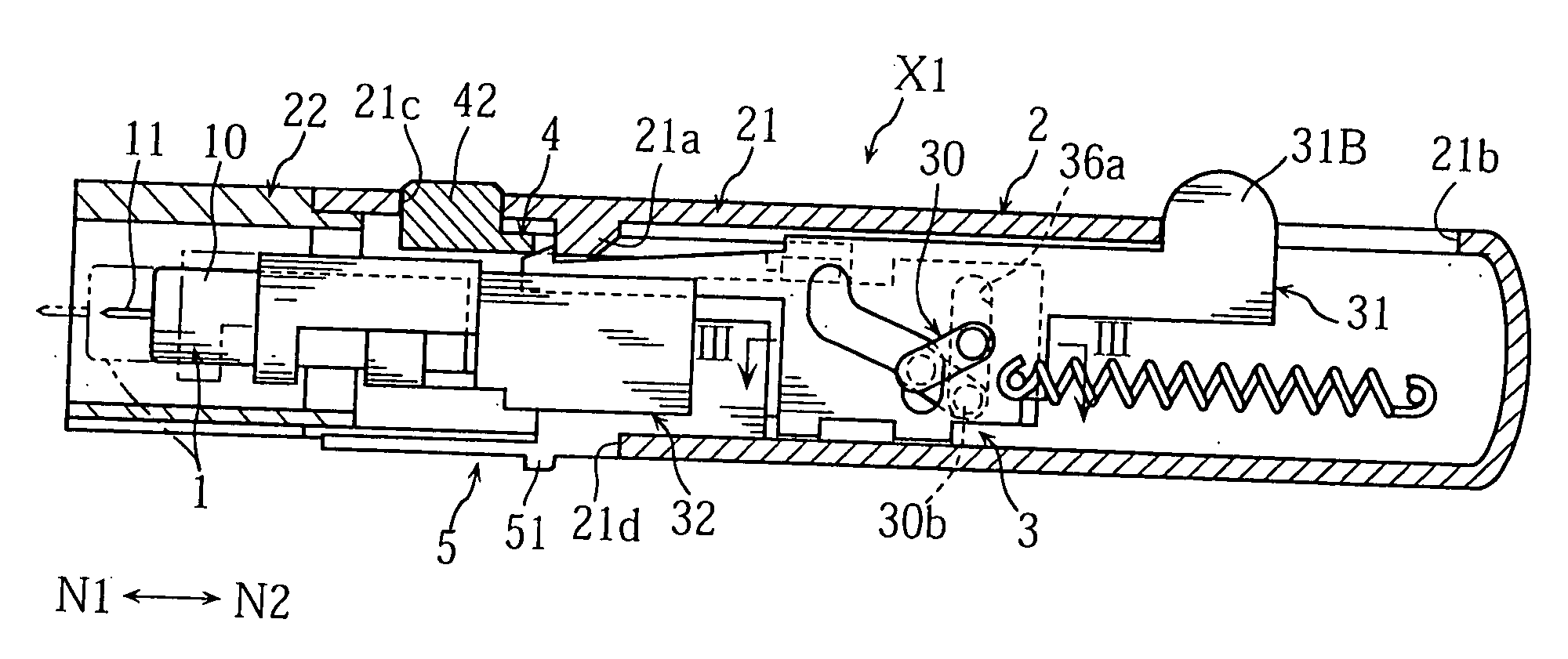
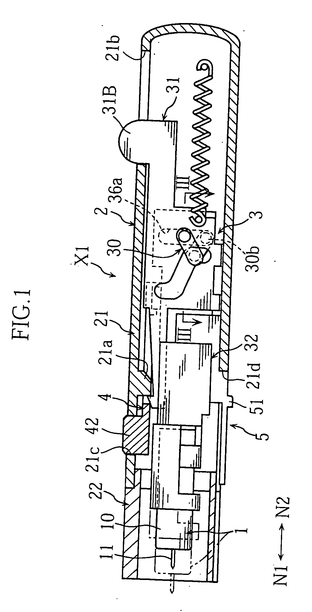
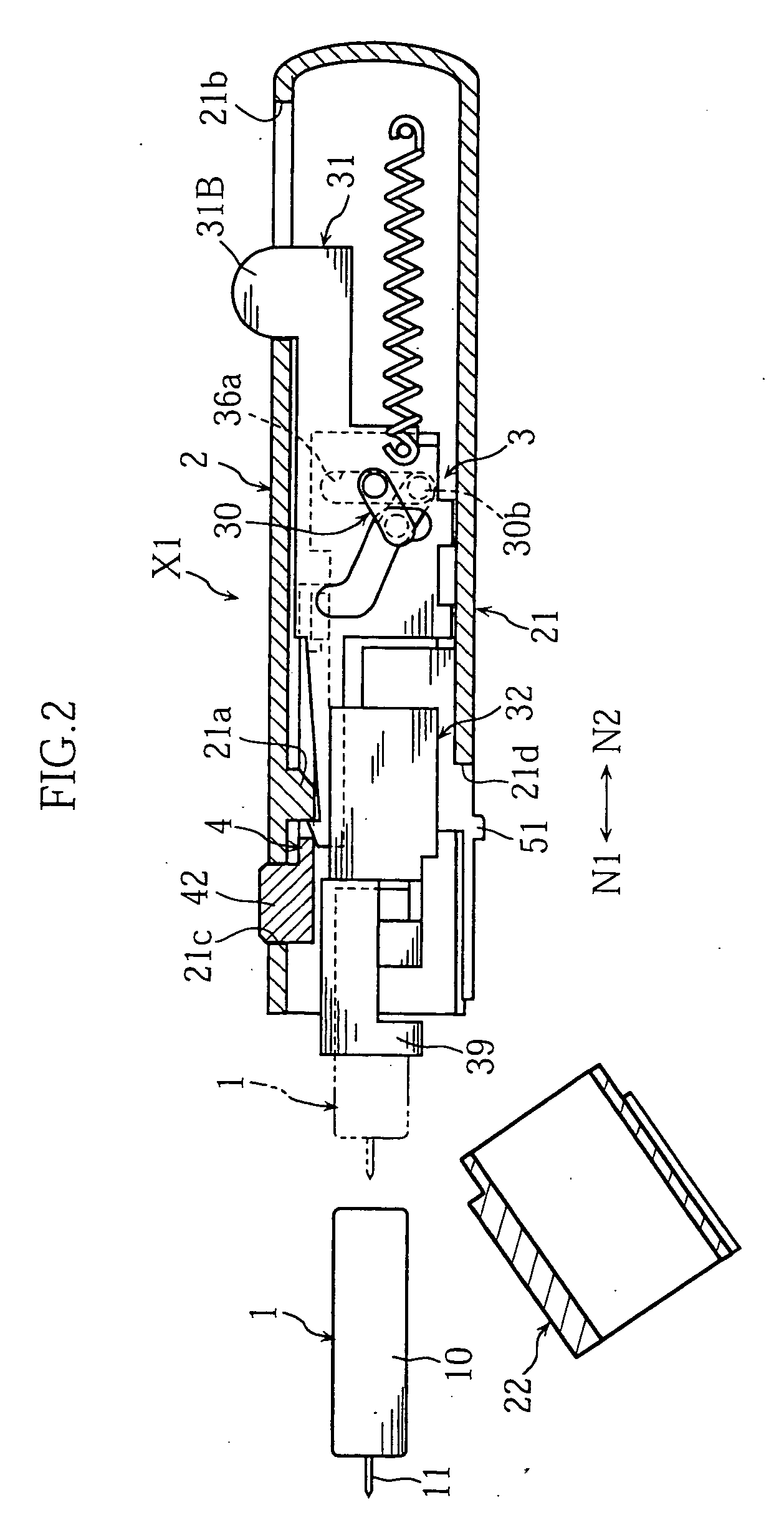
[0066] As shown in FIG. 1, the lancing apparatus X1 is used to lance skin and cause bleeding from the skin by moving a lancet 1 from a wait position (the position at which the lancet 1 is depicted by solid lines in the figure) to a lancing position (the position at which the lancet 1 is depicted by phantom lines in the figure). The lancing apparatus X1 includes a housing 2, a lancet moving mechanism 3, a latch release mechanism 4 and a lancet discharge mechanism 5.

[0067] The lancet 1 is an element to lance skin, as noted above, and held by a lancet holder 32 and moved by the movement of the lancet holder 32, which will be described later. The lancet 1 includes a main body 10 and a lancing needle 11 projecting from the main body and is made disposable, for example. The main body 10 is made of e.g. resin into a columnar configuration. The lancing needle 11 is made of e.g. metal and insert-molded relat...

second embodiment

[0115] Next, the present invention will be described with reference to FIGS. 17-24. In FIGS. 17-24, the elements which are identical or similar to those of the foregoing lancing apparatus X1 are designated by the same reference signs as those used for the foregoing lancing apparatus.

[0116] As shown in FIGS. 17 and 18, in the lancing apparatus X2, the link member 6, the movable plate 7 and the lancet holder 8 are accommodated in the housing 2. By pivoting the link member 6, the movement of the movable plate 7 is converted into reciprocal movement of the lancet holder 8.

[0117] As shown in FIGS. 17 and 19, the link member 6, whose movement is controlled by the movable plate 7, controls the movement of the lancet holder 8. The link member 6 includes a fist arm 61 and a second arm 62.

[0118] The first arm 61 includes a pivot pin 61a. The pivot pin 61a engages a cam groove 70 of the movable plate 7, which will be described later. The second arm 62 includes a pivot pin 62a. The second pin...

third embodiment

[0133] Next, the present invention will be described with reference to FIGS. 25A-25D. In these figures, the elements which are identical or similar to those of the foregoing lancing apparatuses X1 and X2 are designated by the same reference signs as those used for the foregoing lancing apparatuses.

[0134] The lancing apparatus X3 shown in FIGS. 25A-25D differs from the foregoing lancing apparatus X2 (See FIGS. 17 and 24A-24D) in configuration of the cam groove 70B of the movable plate 7B and structure to pull out the lancing needle 11 of the lancet 1 from the skin after sticking in the skin.

[0135] The cam groove 70B includes an inclined groove portion 70d for pivoting the link member 6. The link member 6 includes a pivot pin 61a which moves through the inclined groove portion 70d when the movable plate 7B moves in either of the lancing and the retreating directions N1 and N2.

[0136] The movable plate 7B is supported by a housing 2 via two coil springs Sp and Sp′. The coil spring Sp ...


PUM


Abstract

The present invention provides a lancing apparatus (X1) for moving a lancing element (11) in a lancing direction (N1) from a wait position to a lancing position to lance an intended portion with the lancing element (11). The lancing apparatus (X1) includes a first member (31) which is reciprocally movable in the lancing direction (N1) and in a retreating direction (N2) which is opposite from the lancing direction (N1), and a second member (32) which moves along with the lancing element (11) and performs reciprocal movement in the lancing direction (N1) and the retreating direction (N2) in accordance with the movement of the first member (31).

Description

TECHNICAL FIELD [0001] The present invention relates to a lancing apparatus used to extract blood or tissue from skin, for example. BACKGROUND ART [0002]FIGS. 33A-33C show an example of lancing apparatus. The lancing apparatus 90 shown in the figures includes a lancet 902 which is moved along with a lancet holder 901 by the resilient force of a coil spring 900 to lance skin. As shown in FIG. 33A, in the lancing apparatus 90, the coil spring 900 can be kept in the state for storing the resilient force by latching an engagement claw 903 of the lancet holder 901 to a stepped portion 905 of a housing 904. As shown in FIG. 33B, the latched state can be released by pushing an operation cap 906 to bring an operative portion 907 of the operation cap 906 into contact with the engagement claw 903 and disengaging the engagement claw 903. As shown in FIG. 33C, when the latched state is released, the resilient force of the coil spring 900 acts on the lancet holder 901 to move the lancet 902, alo...

Claims


Application Information

Patent Timeline
IPC IPC(8): A61B17/32A61B5/00A61B5/15
CPCA61B5/1411A61B5/150022A61B5/150412A61B5/15113A61B5/15117A61B5/15128A61B5/1519A61B5/15194A61B5/150503
Inventor FUKUZAWA, MASAHIROUEHATA, YOSHIHARU
Owner ARKRAY INC
Why Eureka
Try Eureka