Boundary scan testing system

a scanning system and scanning technology, applied in the field of scanning scanning, can solve the problems of vendor specific hardware and software, expensive and proprietary, and achieve the effect of reducing the number of scans and avoiding the need for adsorption and detection

Inactive Publication Date: 2006-09-07
SMART EMBEDDED COMPUTING INC
View PDF4 Cites 20 Cited by
  • Summary
  • Abstract
  • Description
  • Claims
  • Application Information

AI Technical Summary

Problems solved by technology

This requires costly test stations that must be local to the unit under test (UUT) and specific connectivity cabling to connect the testing hardware to the UUT.
These often proprietary test stations can vary in configuration from vendor to vendor and are not interchangeable.
The prior art has the disadvantage in that often proprietary and costly vendor specific hardware and software is required to run a boundary scan test.
The prior art has the further disadvantage in that the test equipment must be situated locally to the UUT, as specific and unique cabling is required between the test hardware and the UUT.

Method used


Image

  • Boundary scan testing system
  • Boundary scan testing system
  • Boundary scan testing system

Examples


Embodiment Construction

[0009] The following representative descriptions of the present invention generally relate to exemplary embodiments and the inventor's conception of the best mode, and are not intended to limit the applicability or configuration of the invention in any way. Rather, the following description is intended to provide convenient illustrations for implementing various embodiments of the invention. As will become apparent, changes may be made in the function and / or arrangement of any of the elements described in the disclosed exemplary embodiments without departing from the spirit and scope of the invention.

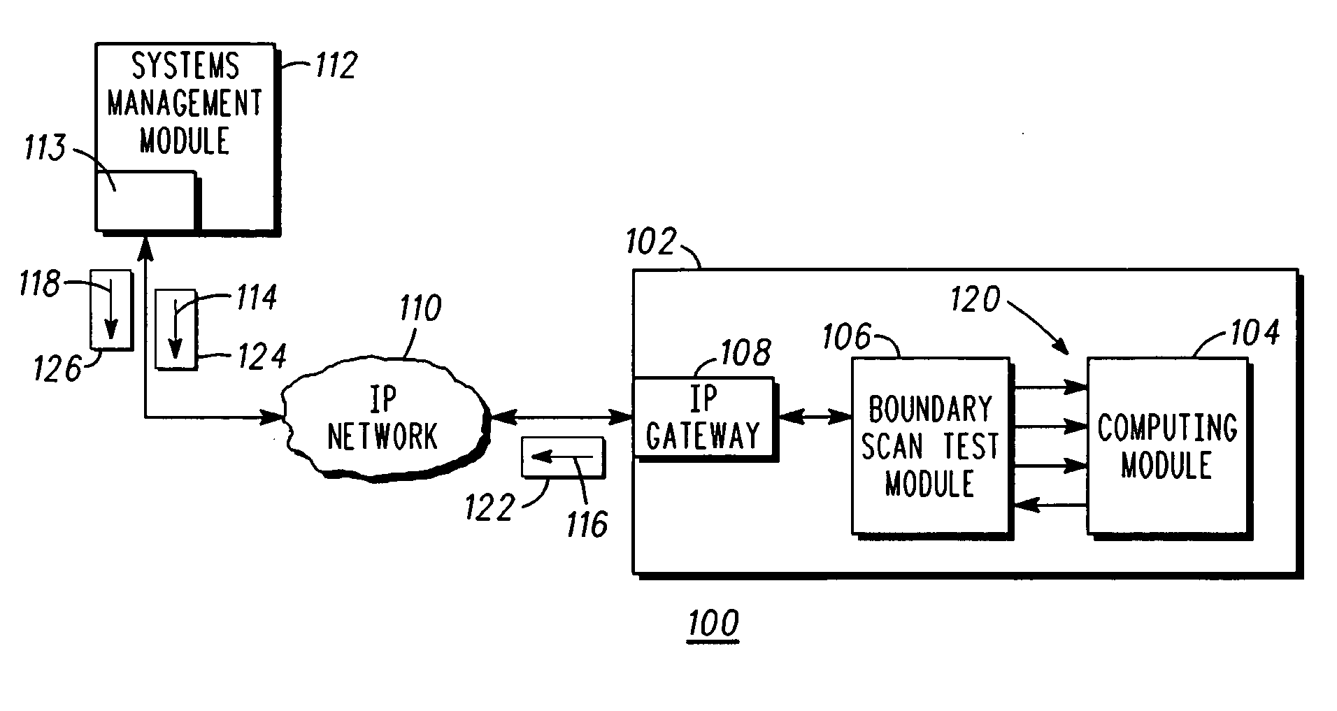
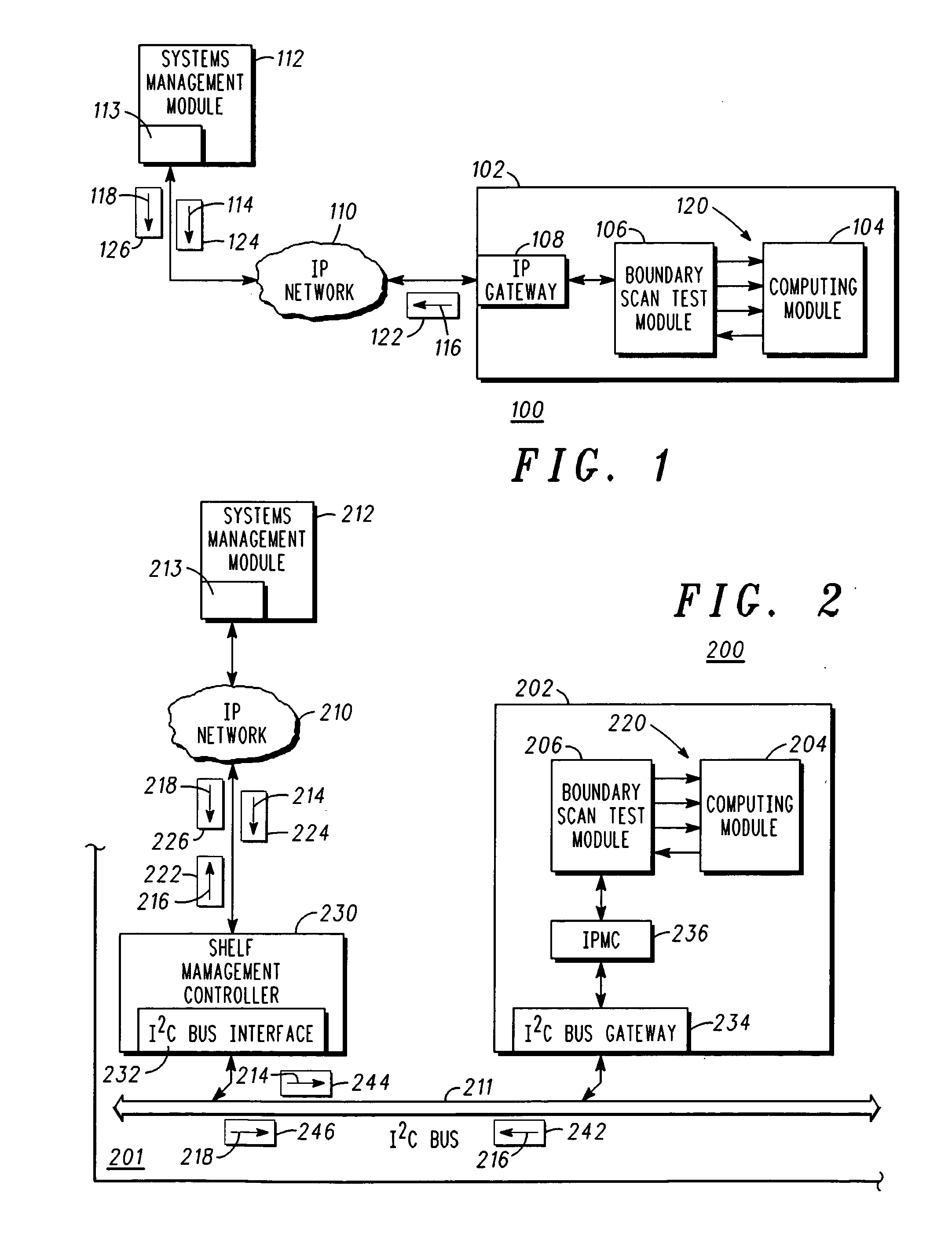
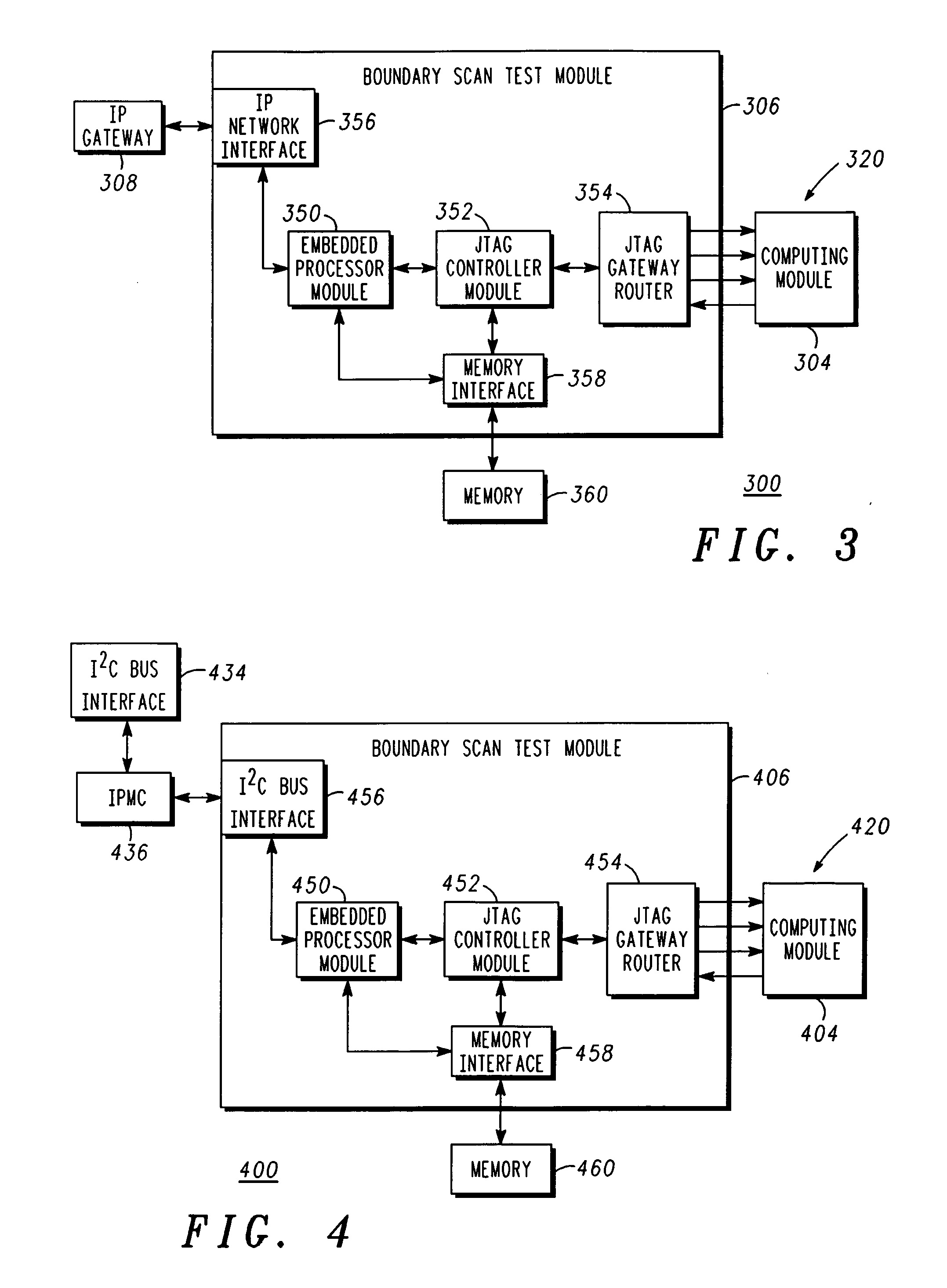
[0010] A detailed description of an exemplary application, namely a boundary scan testing system, is provided as a specific enabling disclosure that may be generalized to any application of the disclosed system, device and method for boundary scan testing in accordance with various embodiments of the present invention.

[0011] Boundary scan testing of integrated circuits (IC's) is defin...


PUM


Abstract

A boundary scan testing system may include a baseboard (102, 202), a computing module (104, 204) coupled to the baseboard, and a boundary scan test module (106, 206, 306, 406) coupled to the computing module, where the boundary scan test module is coupled to execute a boundary scan test (120, 220, 320, 420) on the computing module via a set of boundary scan instructions (114, 214) received remotely over at least one of an IP network (110, 210) and an I2C bus (211).

Description

BACKGROUND OF INVENTION [0001] Current boundary scan testing methods for printed circuit boards utilize vendor-specific hardware that uses software and files compiled to run on that particular hardware. This requires costly test stations that must be local to the unit under test (UUT) and specific connectivity cabling to connect the testing hardware to the UUT. The prior art also requires vendor-specific software to run and diagnose the test results. These often proprietary test stations can vary in configuration from vendor to vendor and are not interchangeable. The prior art has the disadvantage in that often proprietary and costly vendor specific hardware and software is required to run a boundary scan test. The prior art has the further disadvantage in that the test equipment must be situated locally to the UUT, as specific and unique cabling is required between the test hardware and the UUT. [0002] There is a need, not met in the prior art, to perform boundary scan testing of i...

Claims


Application Information

Patent Timeline
Patent Type & Authority Applications(United States)
IPC IPC(8): G01R31/28
CPCG01R31/2815G01R31/28G01R31/2801G01R31/318533
Inventor HALLIDAY, DAVID J.LAKIN, STEVEN J.
Owner SMART EMBEDDED COMPUTING INC
Why Eureka
Try Eureka