Spark ignition engine, controller for use in the engine, ignition coil for use in the engine

a technology for spark ignition and controllers, applied in the direction of electric control, machines/engines, mechanical equipment, etc., can solve the problems of reducing the torque generated by the engine and deteriorating the stability of combustion, and achieve the effect of suppressing the reduction of torque and reducing the main ignition

Active Publication Date: 2006-09-14
HITACHI ASTEMO LTD
View PDF9 Cites 28 Cited by
  • Summary
  • Abstract
  • Description
  • Claims
  • Application Information

AI Technical Summary

Benefits of technology

[0009] One object of the present invention is to provide an engine in which firing and burning can be started at proper timing depending on operating conditions and misfires are reduced.
[0017] Thus, it is possible to provide an engine capable of reducing the main ignition and suppressing a reduction of torque caused by misfire.

Problems solved by technology

This may lead to a risk that torque generated by an engine is reduced and the combustion stability is deteriorated.

Method used


Image

  • Spark ignition engine, controller for use in the engine, ignition coil for use in the engine
  • Spark ignition engine, controller for use in the engine, ignition coil for use in the engine
  • Spark ignition engine, controller for use in the engine, ignition coil for use in the engine

Examples


Embodiment Construction

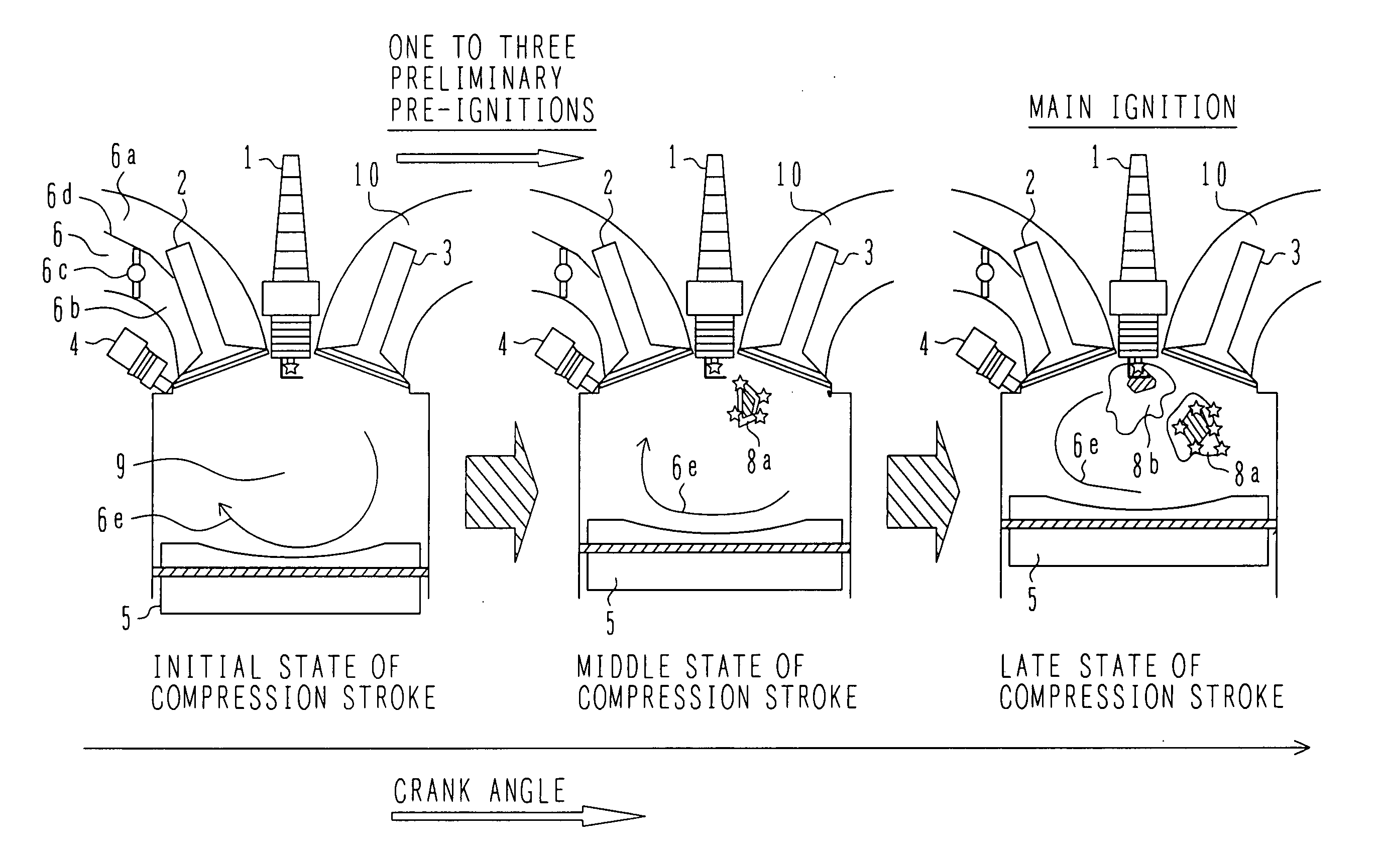
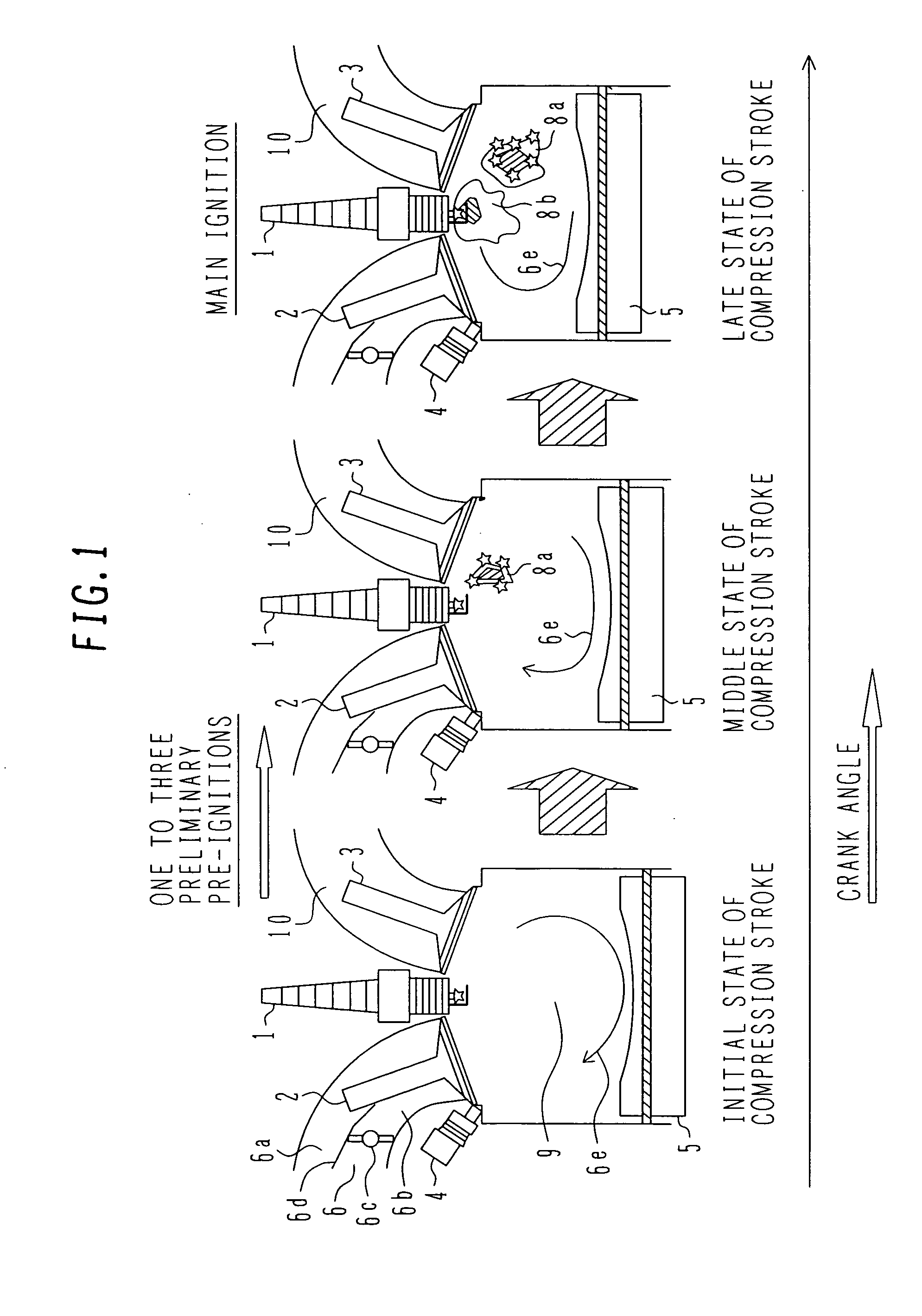
[0033] The basic concept of an embodiment in accordance with the principle of the present invention will be described below with reference to FIG. 1. An engine according to the embodiment has one spark plug 1 per cylinder, which is positioned substantially at a center above a combustion chamber 9. The combustion chamber 9 is enclosed by an intake valve 2, an exhaust valve 3 and a piston 5, and a gas mixture introduced to the combustion chamber 9 is fired by the spark plug 1 and burnt to drive the piston 5 up and down, thereby producing torque. In this embodiment, the present invention is applied to an engine of the so-called in-cylinder direct fuel injection type that an injector 4 directly injects fuel into the combustion chamber 9. FIG. 1 shows successive situations during the compression stroke of the engine in time serial sequence. First preliminary pre-ignition supplies ignition (arc) energy to such a small extent that the gas mixture in the combustion chamber 9 is not entirely...


PUM


Abstract

An engine generating two or more ignition sparks by the same spark plug, which can avoid a torque reduction caused by misfire of main ignition, can start firing and burning at proper timing depending on operating conditions, and can reduce misfires. A novel controller and a novel ignition coil adapted for realizing that engine are also provided. One spark plug and at least one ignition coil are provided per cylinder. When performing a plurality of ignitions during the compression stroke in the cylinder, before main ignition to start firing and burning at proper timing depending on operating conditions of the engine, preliminary pre-ignition is performed to form a fire seed around the spark plug. The main ignition is then performed to cause main burning. Misfire is avoided, appropriate torque can be generated, and combustion stability can be improved.

Description

BACKGROUND OF THE INVENTION [0001] 1. Field of the Invention [0002] The present invention relates to a spark ignition engine, and more particularly to a controller used in the engine for ignition control and an ignition coil for use in the engine. [0003] 2. Description of the Related Art [0004] In a spark ignition engine, it is known to perform spark ignition plural times for the purpose of improving ignitability and combustion stability. For example, JP-A-9-112398 (Patent Document 1) discloses a technique of performing spark ignition plural times during a compression stroke in an engine, which is provided with one spark plug and one ignition coil per cylinder, in order to prevent deterioration of the combustion stability when the ignition timing is advanced for some reason. [0005] Also, JP-A-2002-206473 (Patent Document 2) discloses a technique of providing two ignition coils per cylinder and increasing the degree of freedom in setting the ignition interval in order to prevent a ch...

Claims


Application Information

Patent Timeline
Patent Type & Authority Applications(United States)
IPC IPC(8): F02B3/02F02P15/08F02D43/00
CPCF02D41/3023F02P3/04F02P3/053F02P15/08
Inventor SHIRAISHI, TAKUYA
Owner HITACHI ASTEMO LTD
Why Eureka
Try Eureka