Handheld paint and application tool container

a paint application and tool container technology, applied in the field of hand-held paint and application tool containers, can solve the problems of poor control of the bucket position when dipping paint application tools, unfavorable to accommodate both, and difficult to pick up and set down on the floor, so as to facilitate the painting process and allow the painter to move freely. , the effect of allowing the painter to carry for long periods

Inactive Publication Date: 2006-09-14
CINGEL FRANK JOSEPH
View PDF3 Cites 13 Cited by
  • Summary
  • Abstract
  • Description
  • Claims
  • Application Information

AI Technical Summary

Benefits of technology

[0011] The HANDHELD PAINT AND APPLICATION TOOL CONTAINER, according to the present invention, is generally designed to permit being carried for long periods of time and give the painter freedom to move about without being encumbered by a large paint bucket or a flat horizontal type roller tray while painting trim and other relatively small surfaces. The container is designed to tote an assortment of paint application tools internal to the container, such as a roller and / or paintbrush, or a large and small paintbrush, along with a supply of paint. With this invention the painter can roll the surfaces that are suitable for the roller or other tool being used and finish the areas the larger tool won't reach with the paintbrush. This is a faster process than using a paintbrush alone for trim. Smoothing the rolled surface with the tip of the paintbrush is sometimes desirable to obtain a preferred finish.

Problems solved by technology

Many have storage areas for a paintbrush or a small roller but are unlikely to accommodate both.
Some containers have handles on one side such that they are carried much like a coffee mug, which is tiring, and awkward to pick up and set down on a floor.
Some paint containers are modifications of the swinging bail bucket which are uncomfortable to carry and give poor control over bucket position when dipping the paint application tools.
Some paint containers are designed specifically for use on a ladder, some have that included purpose and some cannot be safely used on a ladder.

Method used


Image

  • Handheld paint and application tool container
  • Handheld paint and application tool container
  • Handheld paint and application tool container

Examples


Embodiment Construction

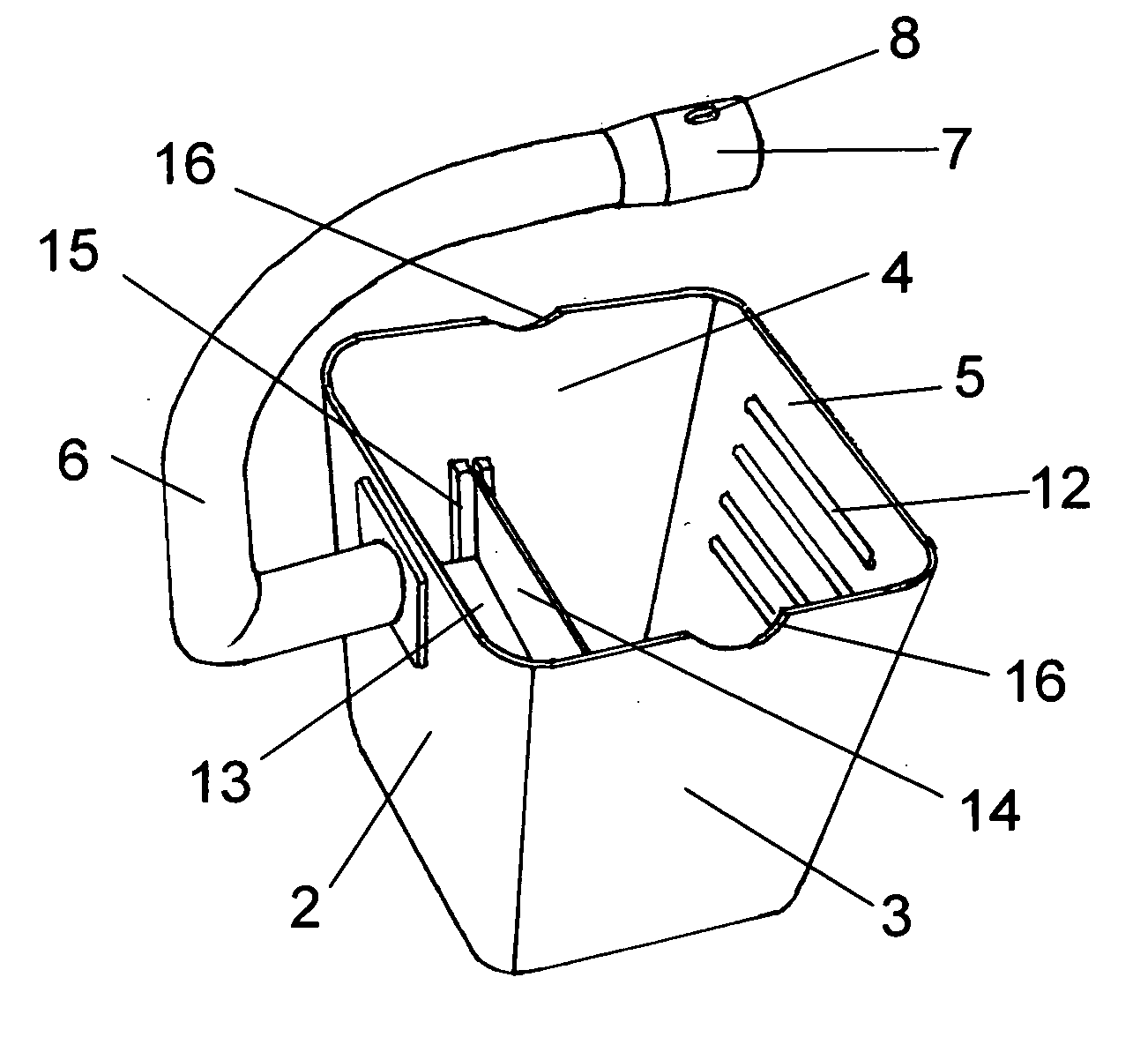
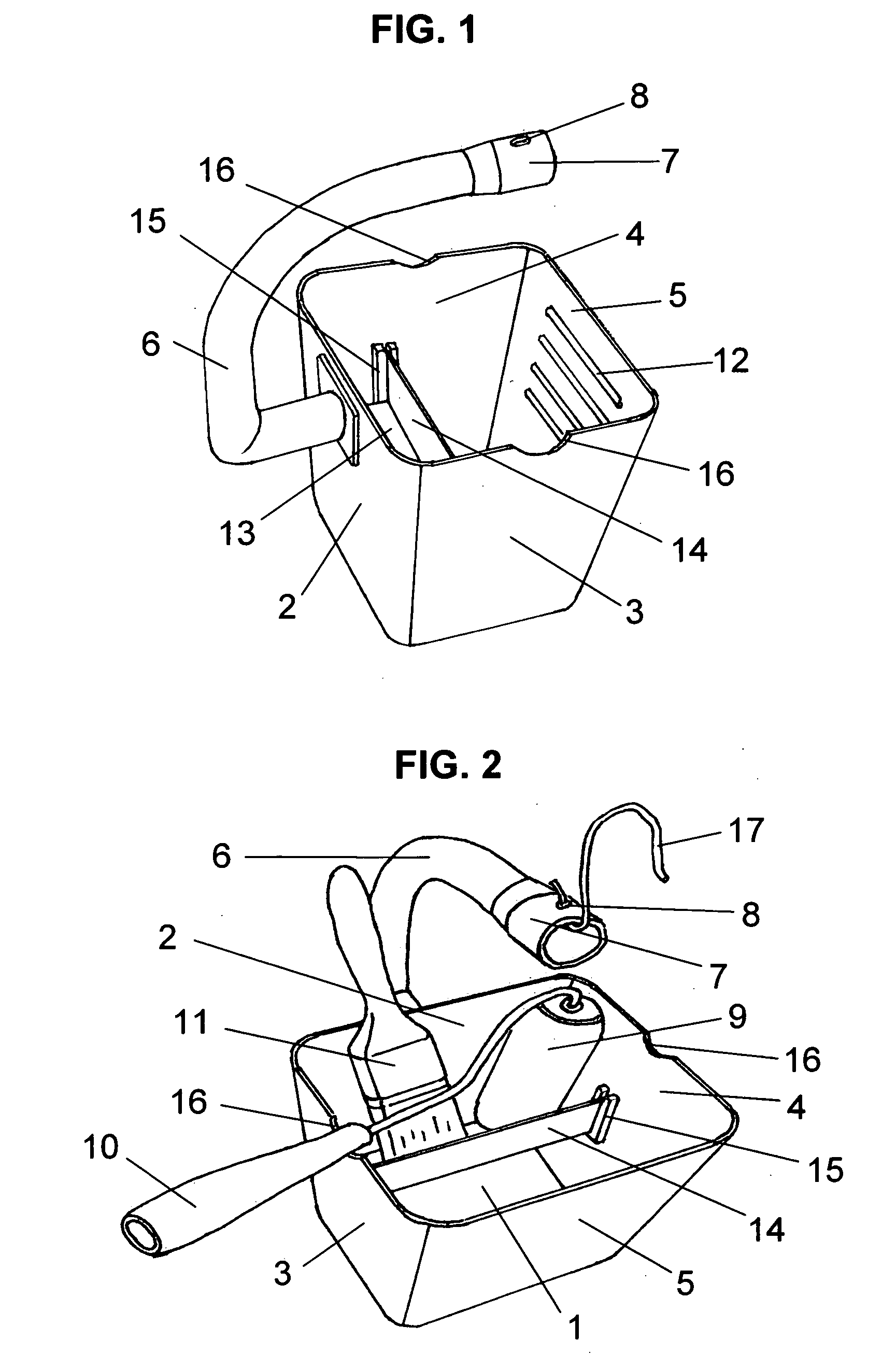
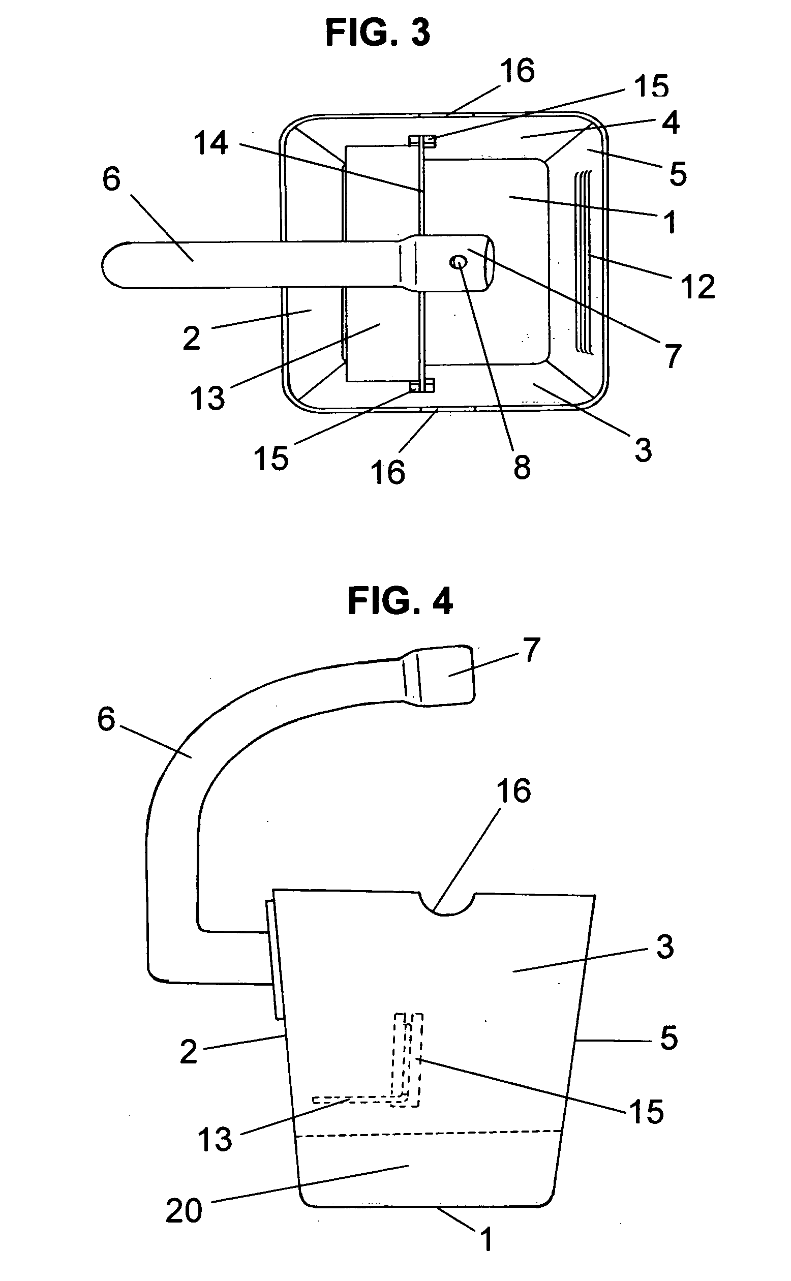
[0025] Referring to FIGS. 1-6 there is shown the preferred embodiment of the invention, attention being called to the fact, however, that the drawings are illustrative only, and that changes may be made in the specific construction illustrated and described, within the scope of the appended claims.

[0026] The preferred container comprises a generally rectangular or square base plate with side walls of equal height that slope outward from the bottom base plate 1, to the top. The base plate 1, back wall 2, left side wall 3, right side wall 4, and front wall 5 are all connected to define an interior volume. Radii adjacent to the base plate are small to increase the contact area of the footprint but large enough to facilitate cleaning paint from the bottom corners of the container. Radii between sides, front, and back walls are more generous for the purpose of pouring unused paint from the container and to provide nesting for the paint roller sleeve 9 of the paint roller assembly.

[0027...


PUM


Abstract

A handheld paint container assembly with a curved handle fixed at one end, positioned for comfort over the center of gravity, and providing good control over container position when dipping paint application tools. An internal confining shelf with capacity to tote a variety of paint application tools. Ideal for applying paint with a smaller roller, and using the paintbrush to tip the rolled surfaces and to paint the areas the roller couldn't reach. It readily hangs on a ladder rung, positioned for convenient and secure access.

Description

REFERENCES CITED U.S. Patent Documents [0001]1,008,856November, 1911Mosher401 / 1212,705,334April, 1955Farrow 15 / 2572,932,838April, 1960Ouellette 15 / 2573,252,613May, 1966McGrath220 / 233,576,045April, 1971Stafford 15 / 2573,595,431July, 1971Bird220 / 6974,860,891August, 1989Biggio206 / 3624,919,298April, 1990Gregory270 / 7364,927,046May, 1990Armstrong220 / 6975,054,661October, 1991Hollje222 / 4655,201,439April, 1993Davies220 / 7355,341,969August, 1994Accardo, et al.222 / 4655,390,888February, 1995Rogers248 / 3185,400,916March, 1995Weber220 / 4955,402,910April, 1995Pilney220 / 7515,493,751February, 1996Misiukowiec, et al. 15 / 2575,546,628August, 1996Silvera 15 / 2575,549,216August, 1996Scholl220 / 6955,634,568June, 1997Wawrzyniak220 / 5105,810,196September, 1998Lundy220 / 7365,836,043November, 1998Rovas 15 / 2575,971,201October, 1999Daw220 / 6976,419,106 B1July, 2002Bebak220 / 5706,513,771 B1February, 2003Tucker248 / 2116,681,924 B2January, 2004Renzello206 / 15U.S. Patent Applications [0002]20030204929 A1November, 2003Rougeau 1...

Claims


Application Information

Patent Timeline
Patent Type & Authority Applications(United States)
IPC IPC(8): B05C21/00
CPCB44D3/125B44D3/128
Inventor CINGEL, FRANK JOSEPH
Owner CINGEL FRANK JOSEPH
Why Eureka
Try Eureka