Vehicular power transmission control apparatus

a technology of transmission control and control apparatus, which is applied in the direction of electric propulsion mounting, transportation and packaging, gearing, etc., can solve the problem of so-called shift shock, which tends to occur in the front-rear direction of the vehicle, and the speed of the acceleration can be effectively increased, so as to achieve the effect of effective increasing the temperature of the lubricating oil

Inactive Publication Date: 2010-09-16
AISIN AI CO LTD
View PDF8 Cites 17 Cited by
  • Summary
  • Abstract
  • Description
  • Claims
  • Application Information

AI Technical Summary

Benefits of technology

[0040]According to the configuration described above, during the vehicle speed is increasing, a timing at which the changeover (shifting) from the (first) IN-Connection State to the OUT-Connection State is carried out is more delayed as the temperature of the lubricating oil is lower, and a timing at which the changeover (shifting) from the OUT-Connection State to the (second) IN-Connection State is carried out comes earlier as the temperature of the lubricating oil is lower. That is, a time period in which the OUT-Connection State is selected becomes shorter, and a time period in which the (first or second) IN-Connection State is selected becomes longer. Consequently, the temperature of the lubricating oil can be effectively increased.
[0041]In this case, it is preferable that the control means be configured so as to adjust the third threshold or the fourth threshold in such a manner that the third threshold becomes larger (or is increased by a positive larger amount) as the temperature of a lubricating oil is lower or the fourth threshold becomes larger (or is increased by a positive larger amount) as the temperature of a lubricating oil is lower. According to the configuration described above, during the vehicle speed is increasing, a timing at which the changeover (shifting) from the (second) IN-Connection State to the non-connection state is carried out is more delayed as the temperature of the lubricating oil is lower, or, during the required driving torque is increasing, a timing at which the changeover (shifting) from the (second) IN-Connection State to the non-connection state is carried out is more delayed as the temperature of the lubricating oil is lower. That is, a time period in which the (second) IN-Connection State is selected lengthens. Consequently, the temperature of the lubricating oil can be effectively increased.
[0042]Furthermore, in this case, the control means may be configured so as to fix the actual connection state of the output shaft of the electric motor to the IN-Connection State in a case where the value correlating with a speed of the vehicle is smaller than or equal to the third threshold, when the temperature of a lubricating oil is lower than a first predetermined value. According to the configuration described above, when the temperature of the lubricating oil is sufficiently low, during the vehicle speed is increasing, a time period where the OUT-Connection State is selected disappears between a time period where the first IN-Connection State is selected and a time period where the second IN-Connection State is selected. Accordingly, a time period where the (first or second) IN-Connection State is selected lengthens. Consequently, the temperature of the lubricating oil can be effectively increased.

Problems solved by technology

Consequently, a rapid change in an acceleration in a front-rear direction of the vehicle (so-called shift shock) tends to occur.

Method used


Image

  • Vehicular power transmission control apparatus
  • Vehicular power transmission control apparatus
  • Vehicular power transmission control apparatus

Examples


Embodiment Construction

[0065]Next will be described embodiments of a vehicular power transmission control apparatus according to the present invention with reference to the drawings.

(Configuration)

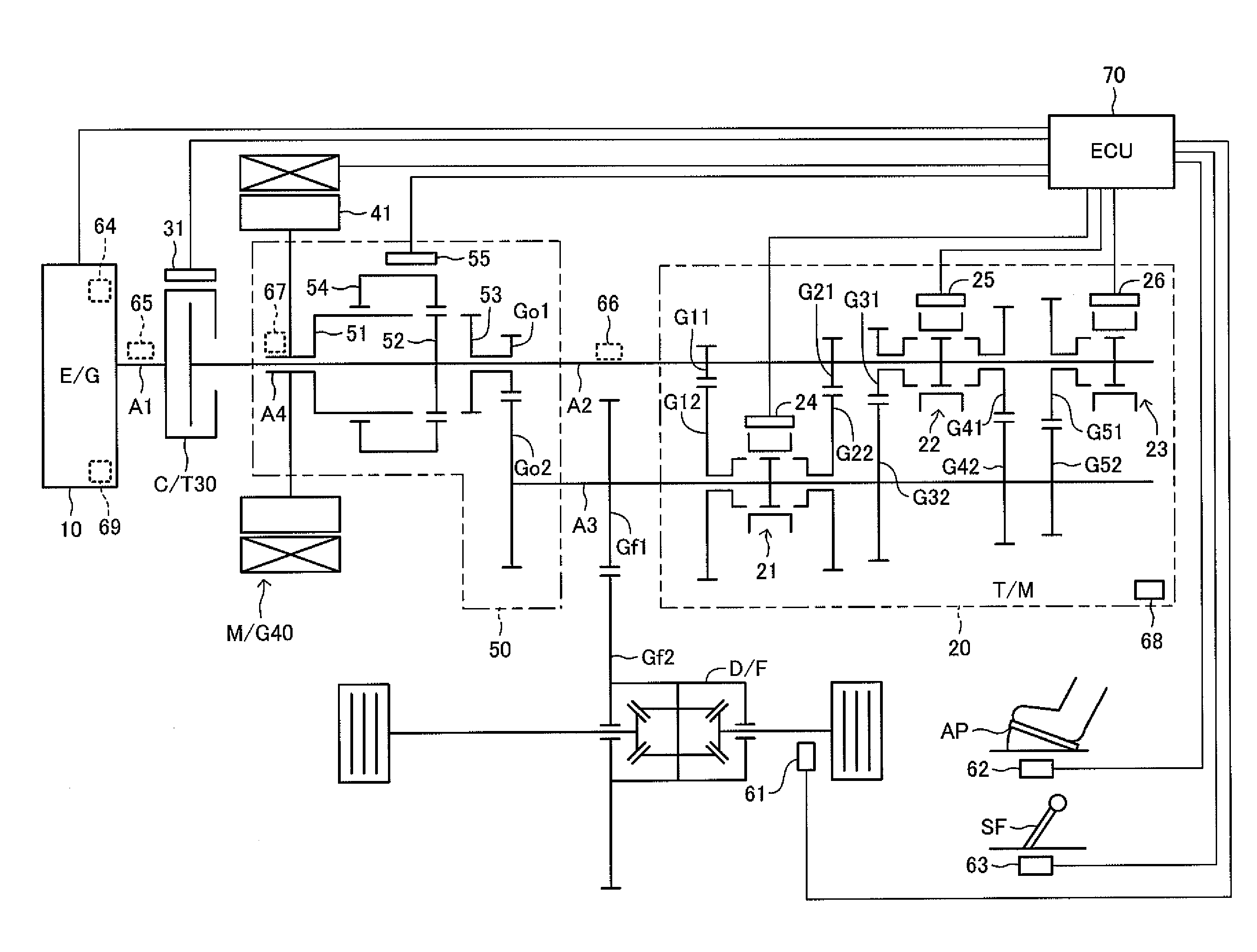
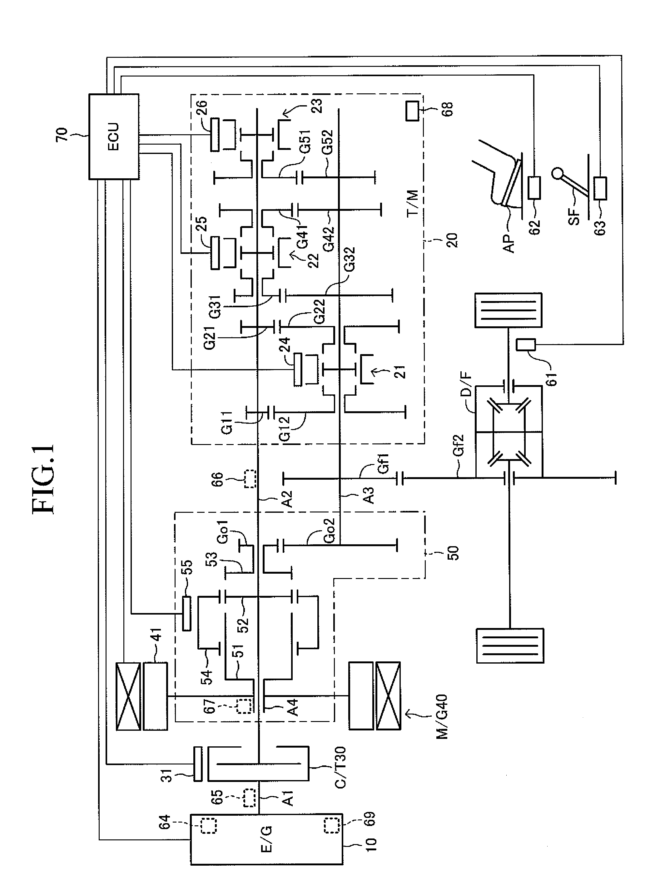
[0066]FIG. 1 shows a schematic configuration of a vehicle mounting a vehicular power transmission control apparatus (hereinafter, referred to as a “present apparatus”) according to an embodiment of the present invention. The present apparatus is applied to the vehicle comprising, as its power sources, an internal combustion engine and a motor generator. The vehicle comprises a so-called automated manual transmission, which uses a multiple gear ratio transmission, but which does not have a torque converter.

[0067]The vehicle comprises the engine (E / G) 10, the transmission (T / M) 20, a clutch (C / T) 30, the motor generator (M / G) 40, and a changeover mechanism 50. The E / G 10 is one of well-known internal combustion engines, including a gasoline engine which uses a gasoline as a fuel and a diesel engine which uses a li...


PUM


Abstract

An apparatus comprises a changeover mechanism which is able to change a connection state of an electric motor output shaft to any one from alternatives consisting of “an IN-Connection State” in which a power transmission path is provided between a transmission input shaft and the electric motor output shaft, “an OUT-Connection State” in which a power transmission path is provided between the transmission output shaft and the electric motor output shaft, and “a neutral connection state” in which no transmission path therebetween is provided. The changeover is carried out based on a combination (area) of a vehicle speed V and a required driving torque T. As for the changeover, an (first, second) IN-connection area is more enlarged and the OUT-Connection area and the neutral connection area are more narrowed, as a temperature of a lubricating oil is lower.

Description

BACKGROUND OF THE INVENTION[0001]1. Field of the Invention[0002]The present invention relates to a vehicular power transmission control apparatus, especially to a vehicular power transmission control apparatus applied to a vehicle comprising an internal combustion engine and an electric motor as power sources.[0003]2. Description of the Related Art[0004]In these days, a so-called hybrid vehicle comprising an internal combustion engine and an electric motor (electric motor generator) as power sources has been developed (refer to, for example, Japanese Unexamined Patent Application Publication No. 2000-224710). In the hybrid vehicle, the electric motor is used as the power source generating a driving torque for driving the vehicle together with the internal combustion engine or by itself, or is used as a power source for starting the internal combustion engine.[0005]Further, the electric motor is used as an electric motor generator for generating a regeneration torque to provide a bre...

Claims


Application Information

Patent Timeline
Patent Type & Authority Applications(United States)
IPC IPC(8): B60W10/10B60W20/00B60K6/365B60K6/387B60K6/48B60K6/547B60W10/02F16H59/10F16H59/18F16H59/42F16H59/72F16H61/02F16H61/68F16H61/682F16H63/46
CPCB60K6/38B60K6/48B60K6/547B60K2006/4808F16H59/72Y10T477/26Y02T10/6221Y02T10/626Y10T477/65Y10T477/23F16H2003/0811Y02T10/62B60K2006/4825
Inventor MIYAZAKI, TAKESHIGEHATORI, HIROKISASAKI, KANTANBA, TOSHIOHAYASHI, YOUSUKE
Owner AISIN AI CO LTD
Why Eureka
Try Eureka