Spread illuminating apparatus

a technology of illumination apparatus and spread, which is applied in the direction of lighting and heating apparatus, planar/plate-like light guides, instruments, etc., can solve the problems of light not being leaked, and achieve the uniformity of illumination light brightness, long time period, and light leakage

Active Publication Date: 2013-06-27
MINEBEAMITSUMI INC
View PDF6 Cites 19 Cited by
  • Summary
  • Abstract
  • Description
  • Claims
  • Application Information

AI Technical Summary

Benefits of technology

[0049]According to this structure, the circuit board is fixed on a fiat part as well when fixing the circuit board to the light guide plate. Thereby, the surface area for adhering the circuit board to the light guide plate increases and the positioning and fixing of the light guide plate and the point light source is stabilized, and thus the uniformity of the brightness of the illumination light can be stably maintained over a longer period of time.
[0050]According to the present invention, in a spread illuminating apparatus including a point light source having a light-emitting surface that emits light toward the forward direction, a circuit board having a mounting surface on which the point light source is mounted, and a light guide plate having an incident light surface on which the point light source is arranged and an emitting surface that emits light that has entered from the incident light surface in a widely spread manner, the circuit board is arranged as that at least a partial portion of the circuit board extends beyond an area where the point light source is mounted so as to be superposed on the light guide plate, a light-reflecting member is arranged on the mounting surface, and a region of the mounting surface in which the light-reflecting member is arranged includes a first region that extends forward from a position corresponding to the center of the light-emitting surface of the point light source. Leakage of light from near the incident light surface of the light guide plate can be thus decreased and an increase in the brightness of the illumination light can be achieved.
[0051]In addition, according to the present invention, in a spread illuminating apparatus including a point light source having a light-emitting surface that emits light toward the forward direction, a circuit board on which the point light source is mounted, and a light guide plate having an incident light surface on which the point light source is arranged and an emitting surface that emits light that has entered from the incident light surface in a widely spread manner, the light guide plate has an inclined part that tapers in thickness from the incident light surface side toward the forward direction, a pedestal having a receiving surface on which the circuit board is arranged is formed in a region excluding a portion in front of the point light source on an inclined surface side of the inclined part, and the receiving surface of the pedestal includes a first surface that is formed on the incident light surface side and a second surface that is formed in front of the first surface and is inclined toward the inclined part side from the first surface side toward the forward direction. Thereby, in a state that the positional relationship between the light-emitting surface of the point light source and the incident light surface of the light guide plate is stably maintained, leakage of light from the inclined part which is formed so as to taper in thickness from the incident light surface side toward the forward direction can be inhibited from progressing to the emitting surface side, and thus the uniformity of the brightness of the illumination light can be improved.

Problems solved by technology

Thereby, such light becomes leaked light not utilized as illumination light.

Method used


Image

  • Spread illuminating apparatus
  • Spread illuminating apparatus
  • Spread illuminating apparatus

Examples


Embodiment Construction

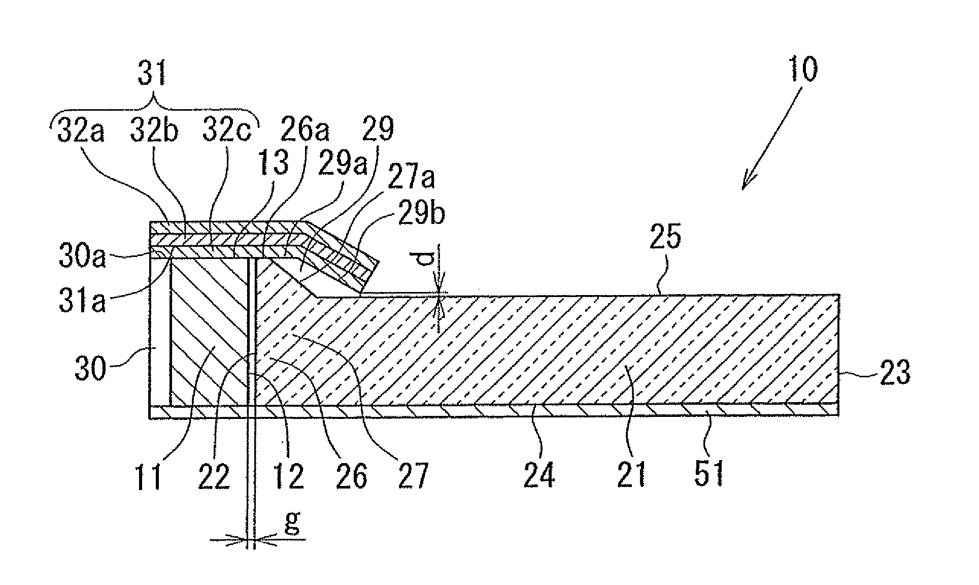
[0057]A spread illuminating apparatus 10 according to embodiments of the present invention will be explained below referring to the drawings. In the drawings shown below, the shape, dimensions, and the like of each constituent component are appropriately exaggerated to facilitate the understanding of the present invention.

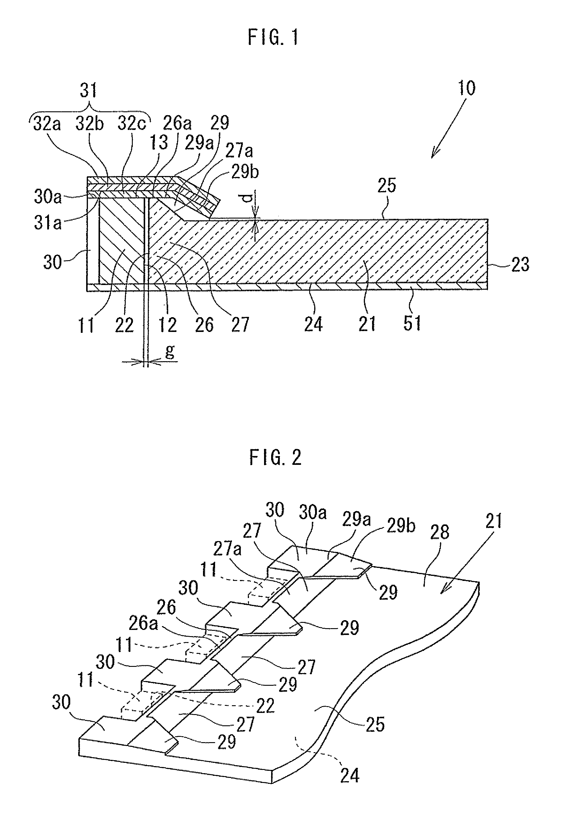
[0058]As shown in FIG. 1, the spread illuminating apparatus 10 includes an LED 11 as a point light source, a light guide plate 21 for emitting light that has been emitted from the LED 11 in a widely spread manner, and an FPC (Flexible Printed Circuit Board) 31 as a circuit board on which the LED 11 is mounted.

[0059]In the present embodiment, the LED 11 is a pseudo white LED including a blue LED and a yellow fluorescent body, and the LED 11 is a so-called side view LED that is formed in an overall rectangular parallelepiped shape and has a light-emitting surface 12 on one side surface. In other words, in the LED 11, a surface (hereinafter also referred to as a “bott...


PUM


Abstract

A spread illuminating apparatus includes a point light source with a light-emitting surface, a circuit board with a mounting surface on which the point light source is mounted, and a light guide plate with an incident light surface and an emitting surface. The circuit board is arranged as that at least a partial portion of the circuit board extends beyond an area where the point light source is mounted so as to be superposed on the light guide plate, a light-reflecting member is arranged on the mounting surface, and a region of the mounting surface in which the light-reflecting member is arranged includes a first region that extends forward from a position corresponding to the center of the light-emitting surface of the point light source.

Description

BACKGROUND OF THE INVENTION[0001]1. Field of the Invention[0002]The present invention relates to a sidelight-type spread illuminating apparatus including a light guide plate in which light sources are arranged at an incident light end surface for emitting widely spread light from emitting portions.[0003]2. Description of the Related Art[0004]As an illumination unit in a liquid crystal display panel, a sidelight-type spread illuminating apparatus (backlight) in which an LED, which is compact and has superior environmental compatibility, is arranged along a side end surface of a light guide plate, has been widely used mainly in the fields of compact portable information devices such as mobile phones and the like. Recently, in order to accommodate even thinner compact portable information devices, light guide plates in which an inclined part that tapers in thickness away from the side end surface (hereinafter, also referred to as the incident light surface) at which the LED is arranged...

Claims


Application Information

Patent Timeline
Patent Type & Authority Applications(United States)
IPC IPC(8): F21V8/00
CPCG02B6/0011G02B6/0018G02B6/0083G02B6/0031G02B6/0021
Inventor KUNIMOCHI, TORU
Owner MINEBEAMITSUMI INC
Why Eureka
Try Eureka