Backlight assembly and liquid crystal display device using the same

a backlight assembly and liquid crystal display technology, applied in lighting and heating devices, applications, instruments, etc., can solve the problems of non-uniform brightness, increase in thickness and volume of lcd devices, and drawbacks of conventional direct-illuminating type lcd devices, so as to optimize brightness and minimize thickness and volume of backlight assemblies

Inactive Publication Date: 2006-07-18
SAMSUNG DISPLAY CO LTD
View PDF1 Cites 9 Cited by
  • Summary
  • Abstract
  • Description
  • Claims
  • Application Information

AI Technical Summary

Benefits of technology

[0015]The present invention provides a backlight assembly having an optimized ratio of the pitch to the gap such that brightness, power consumption, thickness and volume are optimized, thereby realizing a high quality display.
[0016]The present invention also provides an LCD device capable of realizing a high quality display using a backlight assembly having an optimized ratio of the pitch to the gap such that brightness, power consumption, thickness and volume are optimized.
[0017]In one aspect of the invention, there is provided a backlight assembly comprising a receiving container, at least two lamps disposed in the receiving container, and an optical plate for enhancing brightness uniformity of light generated from the lamps, wherein the backlight assembly has a bright line prevention ratio of a pitch to a gap, the ratio being ranged from about 1.3 to about 2.0 so as to prevent a bright line generated from the lamps from being perceived outside the optical plate, the pitch being a distance between centers of two adjacent lamps, the gap being a distance between a center of the respective lamps and a surface of the optical plate, and the surface being opposite to the lamps.
[0019]According to the present invention, the pitch and the gap are precisely controlled to minimize thickness and volume of the backlight assembly, to allow the bright line of the lamp not to be shown, and to provide optimized brightness.

Problems solved by technology

However, the conventional direct-illuminating type LCD device also has disadvantages in that the brightness becomes non-uniform and the thickness and volume of the LCD device increase.
However, even though the light diffusion plate is used, the conventional direct-illuminating type LCD device still has the drawback in that bright lines generated from the lamps are shown from the outside of the light diffusion plate depending upon a pitch and a gap.
On the contrary, if the gap decreases while the pitch is fixed at a constant value, the problem due to brightness is solved, but bright lines are shown and are perceived by a user, so that display failure occurs.
On the contrary, if the pitch decreases while the gap is fixed at a constant value, the brightness is largely enhanced, but the number of the bright lines increases and power consumption increases.

Method used


Image

  • Backlight assembly and liquid crystal display device using the same
  • Backlight assembly and liquid crystal display device using the same
  • Backlight assembly and liquid crystal display device using the same

Examples


first embodiment

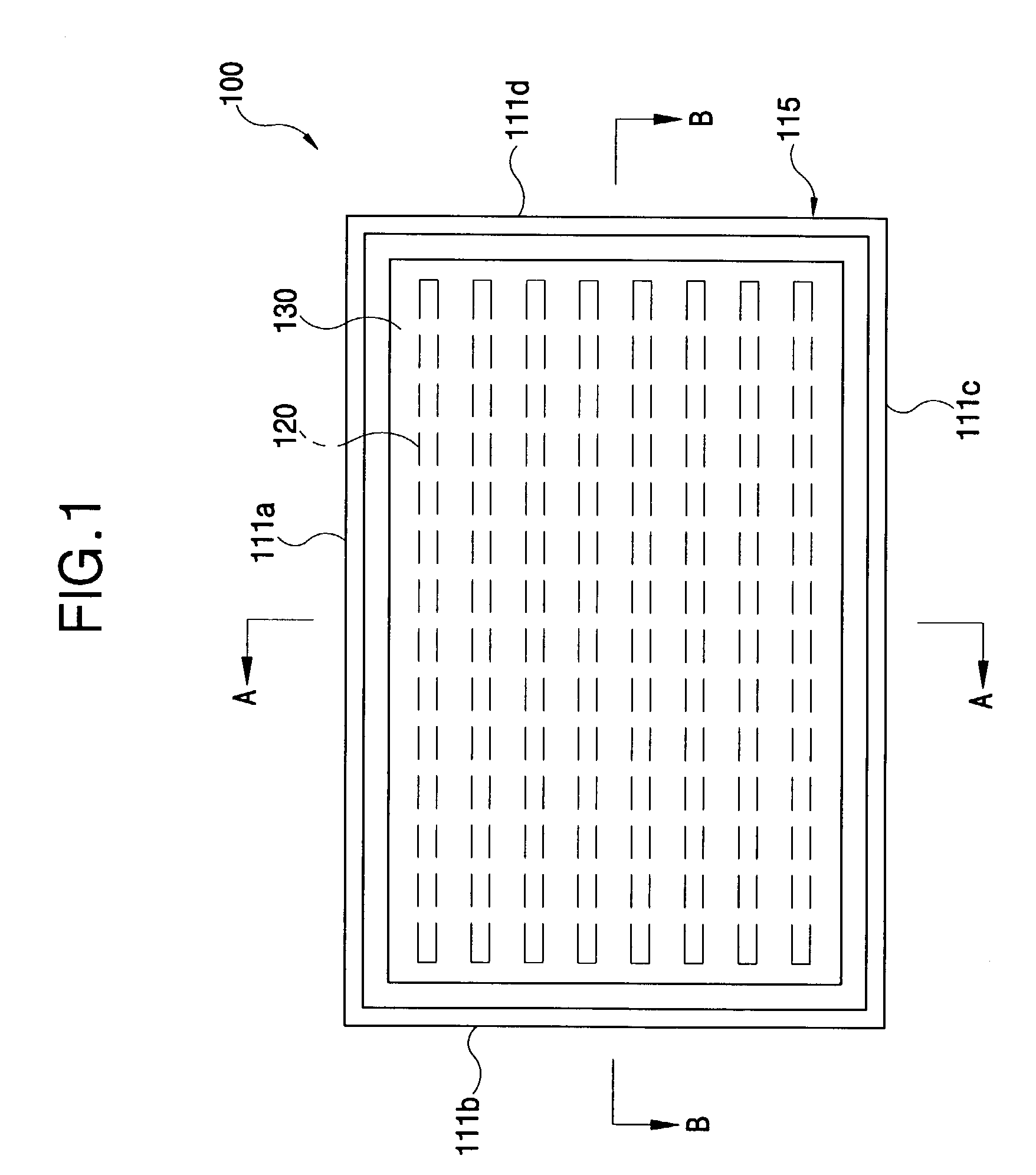
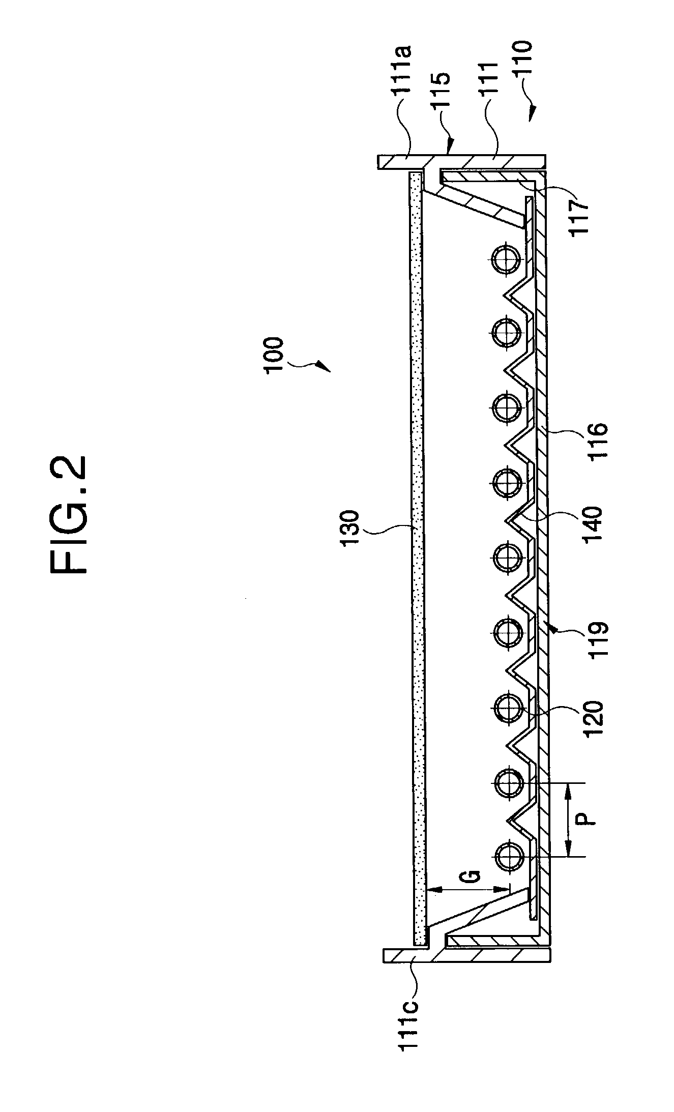
[0032]FIG. 1 is a plan view of a backlight assembly according to the present invention, and FIG. 2 is a sectional view taken along line A—A of FIG. 1.

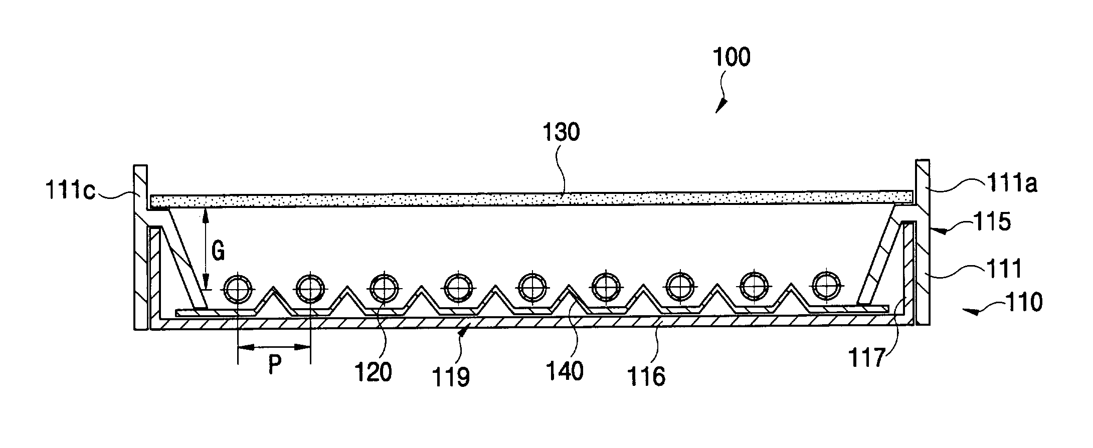
[0033]Referring to FIG. 2, a backlight assembly 100 includes a receiving container 110, a plurality of lamps 120, and an optical plate 130. The reference numeral 140 represents a reflection plate. The reflection plate 140 is installed in the receiving container 110, and reflects the light generated from the lamps 120 toward the optical plate 130.

[0034]The receiving container 110 also includes a receiving frame 115 and a bottom chassis 119.

[0035]Referring to FIG. 1, the receiving frame 115 is comprised of four sidewalls 111a, 111b, 111c, 111d connected with each other. Ends of the lamps 120 are connected to sidewalls 111b and 111d of the receiving frame 115.

[0036]The bottom chassis 119 is comprised of a rectangular bottom plate 116 and a bottom chassis sidewall 117 extended from edges of the bottom plate 116.

[0037]FIG. 3 is a sectional ...

second embodiment

[0065]FIG. 4 is a sectional view of a backlight assembly according to the present invention;

[0066]Referring to FIG. 4 and table 2, when two optical sheets 133 are added on the optical plate 130, the evaluation of the bright line is relatively better (i.e., weaker bright line) compared with the case of one optical sheet shown in table 1, and the brightness is also relatively increased.

[0067]Specifically, in case that the pitch of the lamps and the gap are adjusted to have the bright line prevention ratio of about 2.0 and the optical plate 130 and two optical sheets are used together, the bright line has an intensity that is enough at least to display images. The brightness increases by about 30% or more compared with the case that the optical plate 130 alone is used, so that the display quality is enhanced.

[0068]In case that the pitch of the lamps 120 has a constant value and the gap is adjusted to have a bright line prevention ratio of about 2.3, 1.9 or 1.7, and the optical plate 13...

third embodiment

[0070]FIG. 5 is a sectional view of a backlight assembly according to the present invention.

[0071]Referring to FIG. 5, a brightness-enhanced film (BEF) or a dual brightness-enhanced film (DBEF that is the trademark of a product manufactured by 3M company (Minnesota Mining and Manufacturing company, St. Paul, Minn.)) 135 may be further installed in the backlight assembly 100 when at least one optical sheet is stacked on the optical plate 130, to prevent the light from being absorbed in a lower polarizing plate of the LCD panel and to prevent the brightness from being lowered. It is noted that both the brightness-enhanced film and the dual brightness-enhanced film may be used together.

[0072]In an exemplary embodiment of the present invention shown in table 3 below, a dual brightness-enhanced film is used.

[0073]The dual brightness-enhanced film 135 prevents the light from being absorbed in the lower polarizing plate placed on the backlight assembly of the LCD device. Also, the dual bri...


PUM

PropertyMeasurementUnit
brightnessaaaaaaaaaa
areaaaaaaaaaaa
brightness distributionaaaaaaaaaa

Abstract

Disclosed are a backlight assembly and a liquid crystal display device using the same. A ratio of a pitch, which is an interval between the lamps for supplying light to an LCD panel, to a gap, which is a distance between the center of the lamps and an optical plate, is adjusted to thereby minimize the bright line that badly influences the image display quality, so as to display a high quality image.

Description

BACKGROUND OF THE INVENTION[0001]1. Field of the Invention[0002]The disclosure relates to a backlight assembly and a liquid crystal display device using the same, and more particularly to a backlight assembly and a liquid crystal display device using the same in which bright lines generated from lamps arranged in parallel are prevented, while its volume and thickness are minimized and brightness is maximized.[0003]2. Description of the Related Art[0004]Generally, a liquid crystal display (LCD) device displays images using liquid crystal. Liquid crystal converts light that does not contain information into light containing information to display images. The LCD device includes a liquid crystal (LC) control part for precisely controlling the liquid crystal and a light supply part for supplying light to the LC control part.[0005]In particular, the light supply part greatly influences the display quality of the LCD device. Specifically, the light supply part influences display brightnes...

Claims


Application Information

Patent Timeline
Patent Type & Authority Patents(United States)
IPC IPC(8): F21S4/00F21S2/00F21S8/04F21Y103/00G02F1/13357
CPCG02F1/133604G02F2001/133613G02F1/133605G02F1/133613G02F1/1335
Inventor LEE, KEUN-WOOPARK, JONG-DAEBANG, CHANG-YOUNGLEE, TAE-JINLEE, JAE-SANGLEE, JEONG-HWANJUNG, JAE-HOCHOI, YONG-SEOK
Owner SAMSUNG DISPLAY CO LTD
Why Eureka
Try Eureka