Image forming device

a technology of forming device and fixing roller, which is applied in the direction of instruments, electrographic process equipment, optics, etc., can solve the problems of deformation of resin lens, inability to configure an image forming device simultaneously, and hardening of toner housed within the developing unit, so as to shorten the time for turning the power supply and reliably prevent the effect of wasting the heat of the fixing roller

Inactive Publication Date: 2007-05-03
KYOCERA DOCUMENT SOLUTIONS INC
View PDF5 Cites 20 Cited by
  • Summary
  • Abstract
  • Description
  • Claims
  • Application Information

AI Technical Summary

Benefits of technology

[0025] According to the present invention, the voltage output from the thermoelectric conversion device to the cooling fan is higher when a static cooling fan starts to be driven than when a driven cooling fan stops being driven. Therefore the time period that the cooling fan is operated after the power supply to the image forming device is turned OFF can be longer than with conventional art. Also the temporary rise in temperature within the image forming device after the power to the image forming device is turned OFF due to the waste heat of the fixing roller can be reliably prevented. Also, the time at which the cooling fan starts to be driven can be delayed relative to the time that thermoelectromotive force is generated in the thermoelectric conversion device. Therefore it is possible to shorten the time from turning the power supply to the image forming device ON until the fixing roller reaches the temperature required for fixing.

Problems solved by technology

This can cause hardening of the toner housed within the developing unit, or deformation of the resin lens within the laser scanner unit for irradiating the photosensitive drum with laser light.
In this way, the temperature within the image forming device after the power is turned OFF is higher than the temperature while the power is ON, so the above-mentioned problems can occur.
In this way, the conventional configuration of an image forming device cannot simultaneously achieve both short time from turning the power supply to the image forming device ON until the fixing roller reaches the temperature necessary for fixing, and prevention of a temporary rise in temperature within the image forming device after the power supply to the image forming device is turned OFF.

Method used


Image

  • Image forming device
  • Image forming device
  • Image forming device

Examples


first preferred embodiment

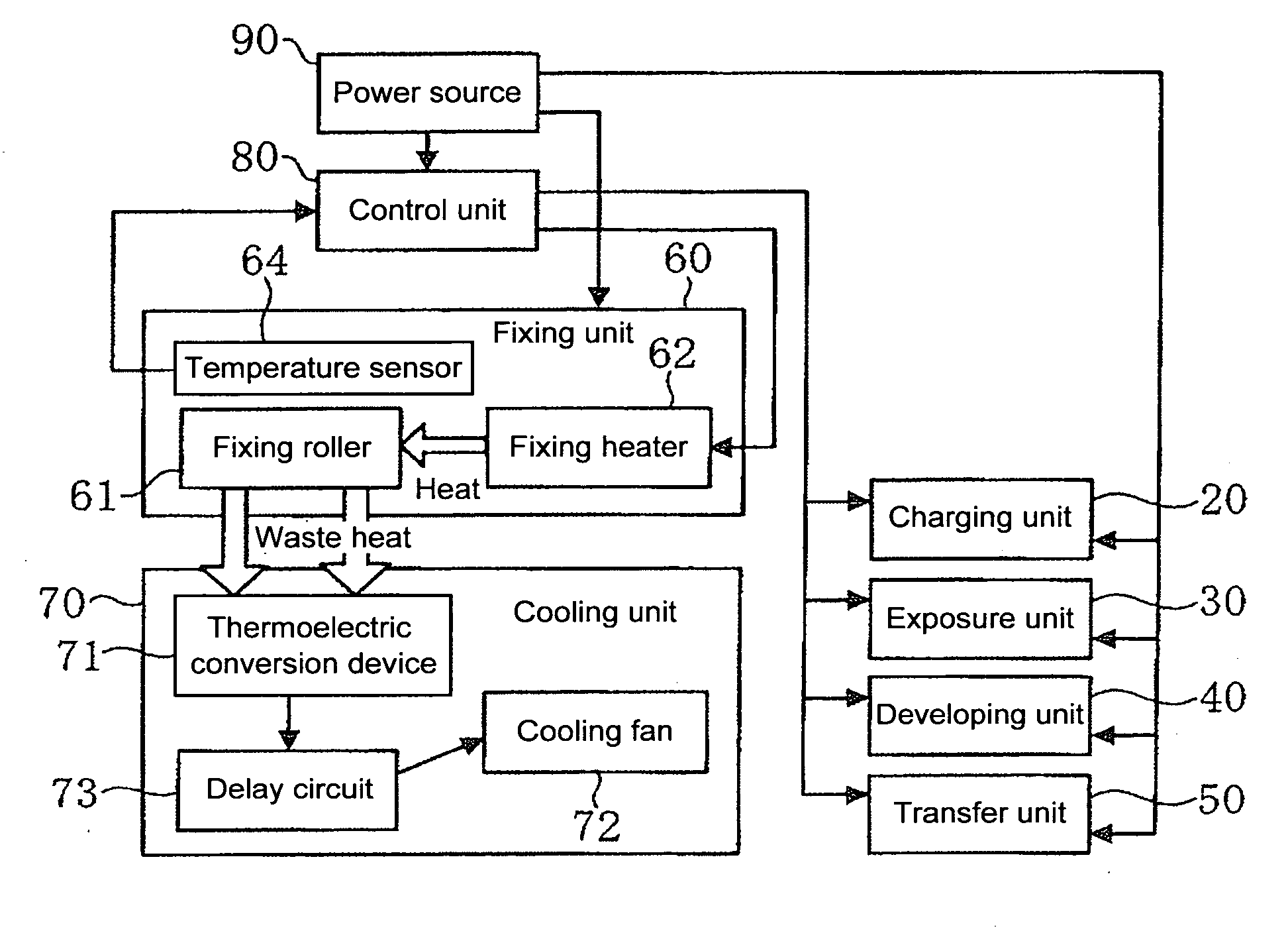
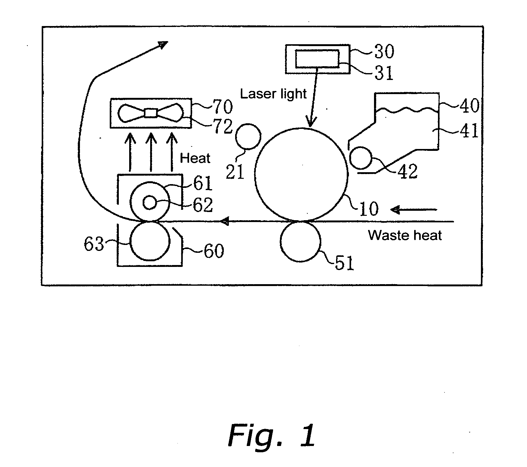
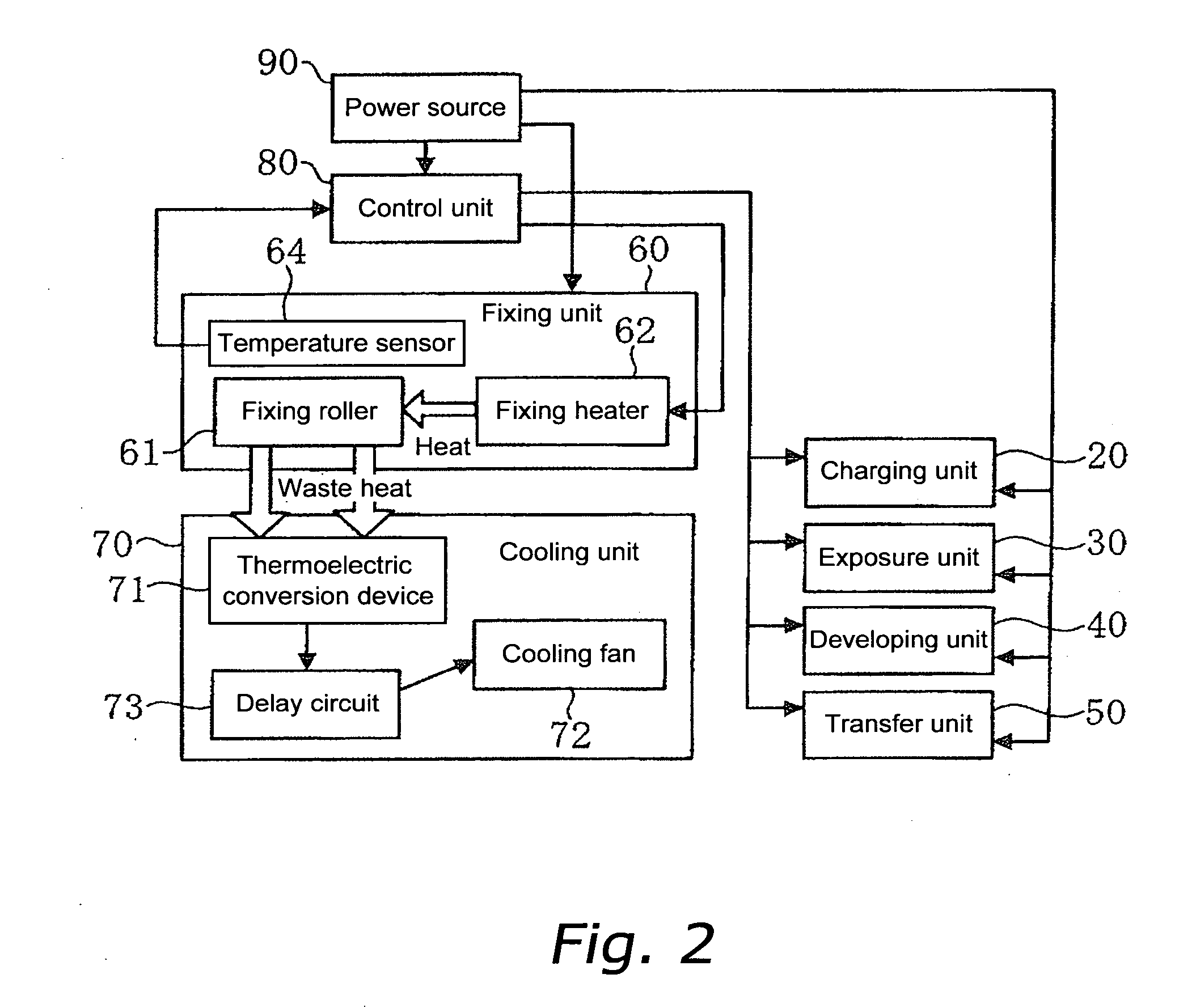
[0036] As shown in FIG. 1 and FIG. 2, the image forming device according to a first preferred embodiment includes a photosensitive drum 10; a charging unit 20 that charges the entire surface of the photosensitive drum 10; an exposure unit 30 that irradiates the surface of the photosensitive drum 10 with laser light; a developing unit 40 that develops by applying toner 41 to the surface of the photosensitive drum 10; a transfer unit 50 that transfers the toner 41 adhering to the surface of the photosensitive drum 10 to sheets; a fixing unit 60 that fixes toner 41 that has been transferred onto a sheet onto the sheet; and a cooling unit 70 that generates electricity using waste heat from the fixing unit 60 and cools the exposure unit 30 and the developing unit 40.

[0037] Also, as shown in FIG. 2, the image forming device includes a control unit 80 that controls the operation of all the devices within the image forming device, and a power supply unit 90 that supplies electrical power t...

second preferred embodiment

[0056] The second preferred embodiment of the present invention is a modification of the image forming device according to the first preferred embodiment. The following is an explanation of the points in which the image forming device according to the second preferred embodiment differ from the first preferred embodiment.

[0057] In the image forming device according to the present preferred embodiment, in the cooling unit 70 a switching circuit 74 including a comparator as shown in FIG. 6 is provided between the thermoelectric conversion device 71 and the cooling fan 72, as shown in FIG. 5.

[0058] The switching circuit 74 includes an input terminal Vin at which the voltage output from the thermoelectric conversion device 71 is input; a resistance R1 a first end of which is connected to ground; a resistance R2 a first end of which is connected to a second end of the resistance R1 and a second end of which is connected to the power supply; a condenser C1 a first end of which is connec...


PUM


Abstract

An image forming device in which a fixing unit is powered from the power supply, and a cooling unit is driven by electricity obtained by supplying waste heat from the fixing roller to a thermoelectric conversion device. After turning the image forming device ON, when the temperature of the fixing roller reaches a certain temperature thermoelectromotive force is generated in the thermoelectric conversion device. When the power supply is turned OFF, the thermoelectromotive force in the thermoelectric conversion device becomes zero when the temperature of the fixing roller drops to a certain temperature. Also, a delay circuit is provided between the thermoelectric conversion device and the cooling fan, so supply of electricity to the cooling fan is later than the time that thermoelectromotive force is generated, and the time that power supply to the cooling fan stops is also later than the time that the thermoelectromotive force becomes zero.

Description

FIELD OF THE INVENTION [0001] The present invention relates to an image forming device, and more particularly to cooling the developing system and optical system using the waste heat of the fixing unit. BACKGROUND INFORMATION [0002] In image forming devices such as copiers, printers, and facsimiles, in the fixing unit in which toner images are fixed to sheets, fixing rollers are heated by heaters so that when a sheet passes the fixing roller the toner adhering to the sheet is melted. Although part of the heat of the heated fixing roller is used as heat energy to melt the toner, most of the heat is dissipated to the surroundings from the fixing roller as waste heat. Therefore technology is proposed in which the waste heat of the fixing roller is converted into electrical energy using a thermoelectric conversion device based on the Seebeck effect. [0003] When high temperature waste heat emitted from the fixing roller to the surroundings is transferred outside the fixing unit, the temp...

Claims


Application Information

Patent Timeline
Patent Type & Authority Applications(United States)
IPC IPC(8): G03G15/00
CPCG03G15/80
Inventor MASHIKI, MASAMI
Owner KYOCERA DOCUMENT SOLUTIONS INC
Why Eureka
Try Eureka