
Critical alignment of parallax images for autostereoscopic display

a parallax image and autostereoscopic technology, applied in the visual arts, can solve the problems of cumbersome alignment of multiple cameras at a common scene, inability to readjust image alignment, and difficulty in proper alignment and color/luminance matching of cameras

Active Publication Date: 2006-09-14
VISION III IMAGING
View PDF11 Cites 61 Cited by
  • Summary
  • Abstract
  • Description
  • Claims
  • Application Information

AI Technical Summary

Benefits of technology

[0012] A second aspect of the invention includes a system for generating a set of aligned parallax images. The system includes a computer and an application running on the computer. The application is configured to display alternating views of

Problems solved by technology

Further, once the images from the cameras have been captured, the alignment of the images cannot be readjusted.
While each of these described methods and systems can be used to capture images for three-dimensional image display, there are problems associated with each.
Aligning multiple cameras at a common scene is cumbersome.
Not only are there multiple cameras to carry and to position, but proper alignment and color / luminance matching of the cameras can be difficult.
Even after alignment, the cameras still may not provide a desired degree of image alignment for later display.
Also, none of these three-dimensional display methods are suitable for use with randomly acquired images or with images extracted from a conventional video image stream (e.g., sequence) or images with parallel views, for example.

Method used

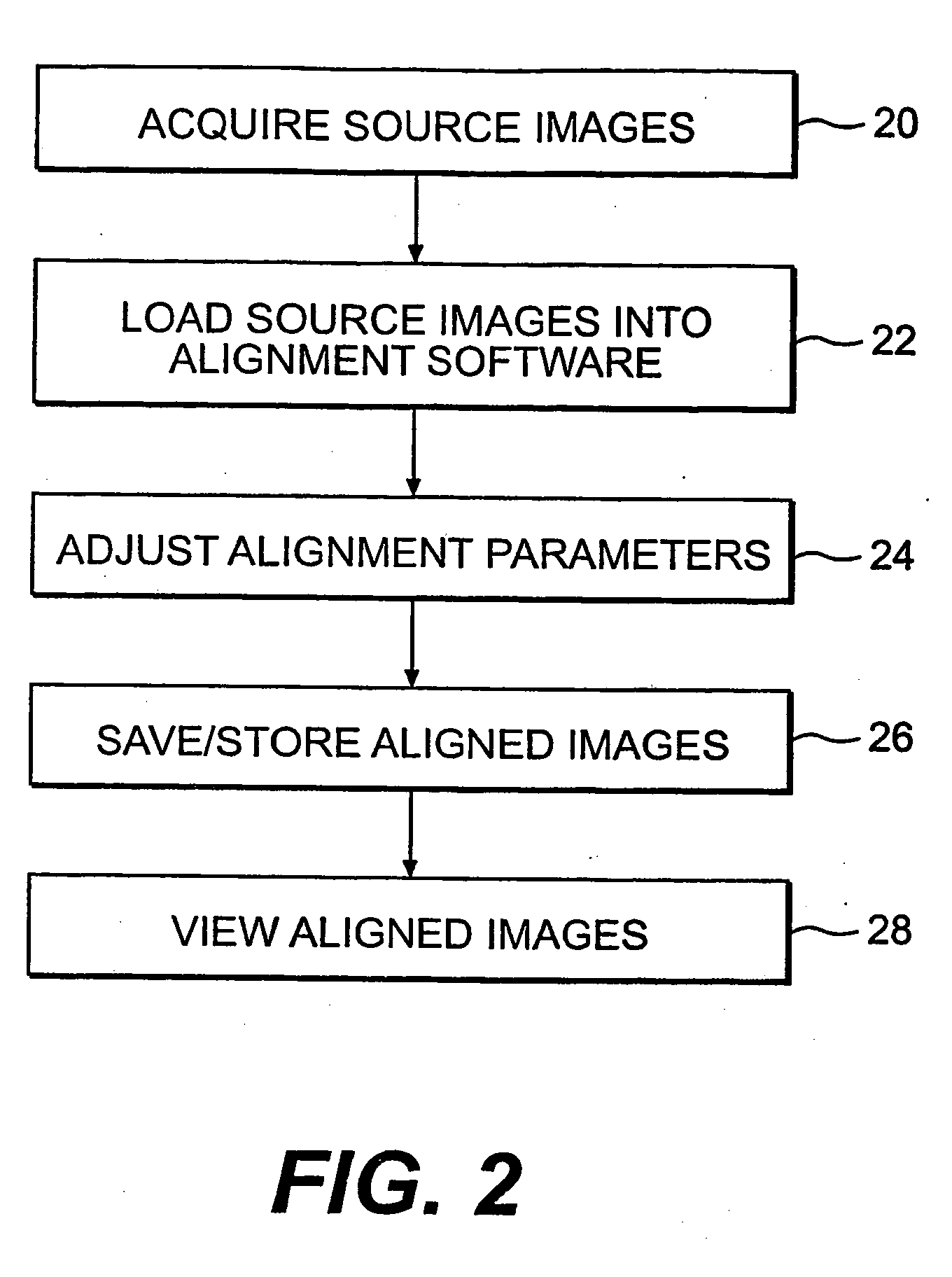

Image

  • Critical alignment of parallax images for autostereoscopic display
  • Critical alignment of parallax images for autostereoscopic display
  • Critical alignment of parallax images for autostereoscopic display

Examples


Embodiment Construction

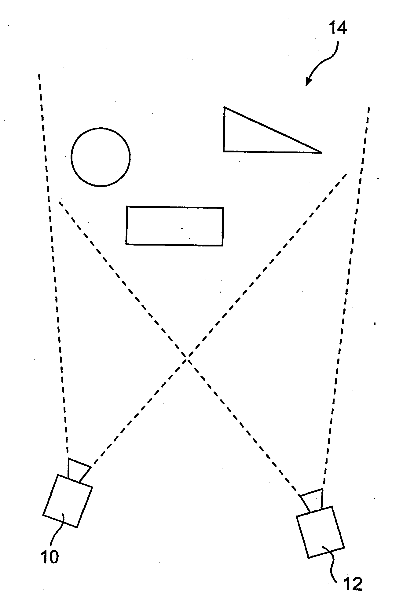
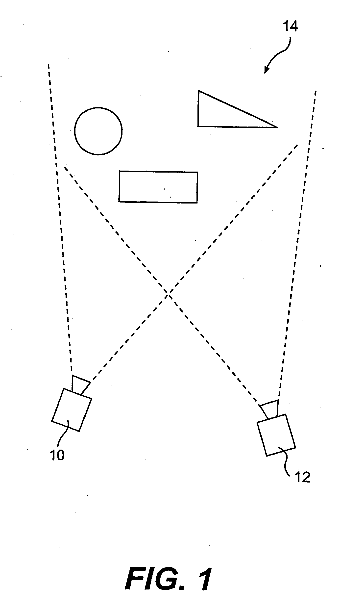
[0017] One exemplary embodiment of the present invention includes a method for creating an autostereoscopic display by manipulating parallax images to create a resultant moving image. The resultant moving image may provide an autostereoscopic display and may be viewed on a conventional screen (e.g., a TV, computer monitor, a projection screen, moving image display, or any other type of display on which a moving image may be shown) As discussed above, parallax images include two or more images with overlapping visual fields but different points of view. For example, as illustrated in FIG. 1, a camera 10 may capture a first set of images and a camera 12 may capture a second set of images of a common scene 14 while being displaced from one another. The resulting sets of images from cameras 10 and 12 will be parallax images. That is, the set of images from camera 10 and the set of images from camera 12 will include some duplicated visual information by virtue of the fact that cameras 10...


PUM


Abstract

A method is provided for generating an autostereoscopic display. The method includes acquiring a first parallax image and at least one other parallax image. At least a portion of the first parallax image may be aligned with a corresponding portion of the at least one other parallax image. Alternating views of the first parallax image and the at least one other parallax image may be displayed.

Description

FIELD OF THE INVENTION [0001] The present invention relates to the visual arts field and more particularly to autostereoscopic imaging methods for producing two-dimensional images that, upon display, can be perceived to be three-dimensional without the use of special viewing aids. BACKGROUND [0002] The production of two-dimensional images that can be displayed to provide a three-dimensional illusion has been a long-standing goal in the visual arts field. Methods and apparatus for producing such three-dimensional illusions have to some extent paralleled the increased understanding of the physiology of human depth perception, as well as, developments in image manipulation through analog / digital signal processing and computer imaging software. [0003] Binocular (i.e., stereo) vision requires two eyes that look in the same direction, with overlapping visual fields. Each eye views a scene from a slightly different angle and focuses it onto the retina, a concave surface at the back of the ...

Claims


Application Information

Patent Timeline
IPC IPC(8): G02B27/22H04N13/122
CPCG02B27/2214H04N13/0018H04N13/0296H04N13/02H04N13/026H04N13/0025H04N13/20H04N13/122H04N13/133H04N13/139H04N13/261H04N13/271H04N13/282H04N13/296H04N13/302H04N13/327G02B30/27
Inventor MARTIN, MICHAEL BURGESSMAYHEW, CHRISTOPHER ALAN
Owner VISION III IMAGING
Learn More