
Transmit power adjustment based on estimated electrical length of a loop

a technology of transmission power and loop, applied in the field of communication systems, can solve the problems of reducing the performance of dsl modems, limiting the length of dsl loops, and estimation of loop lengths, so as to reduce far-end cross-talk, transmit power, and accurate estimate of electrical lengths

Inactive Publication Date: 2006-09-14
AVAGO TECH INT SALES PTE LTD
View PDF6 Cites 5 Cited by
  • Summary
  • Abstract
  • Description
  • Claims
  • Application Information

AI Technical Summary

Benefits of technology

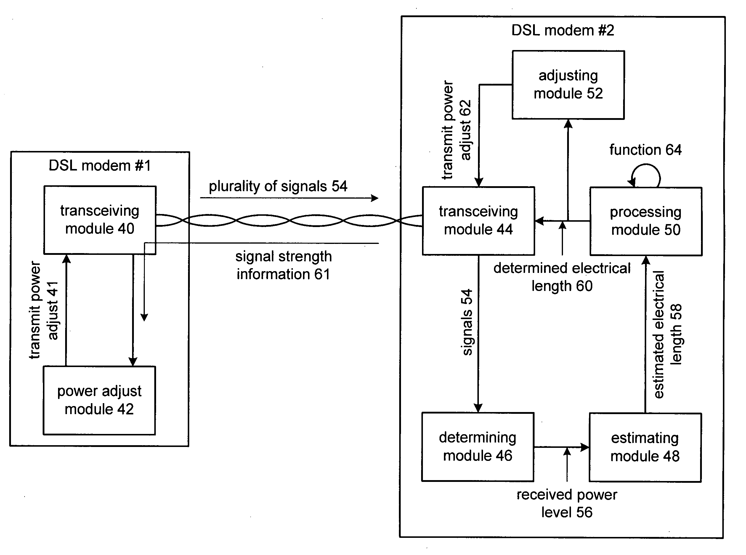
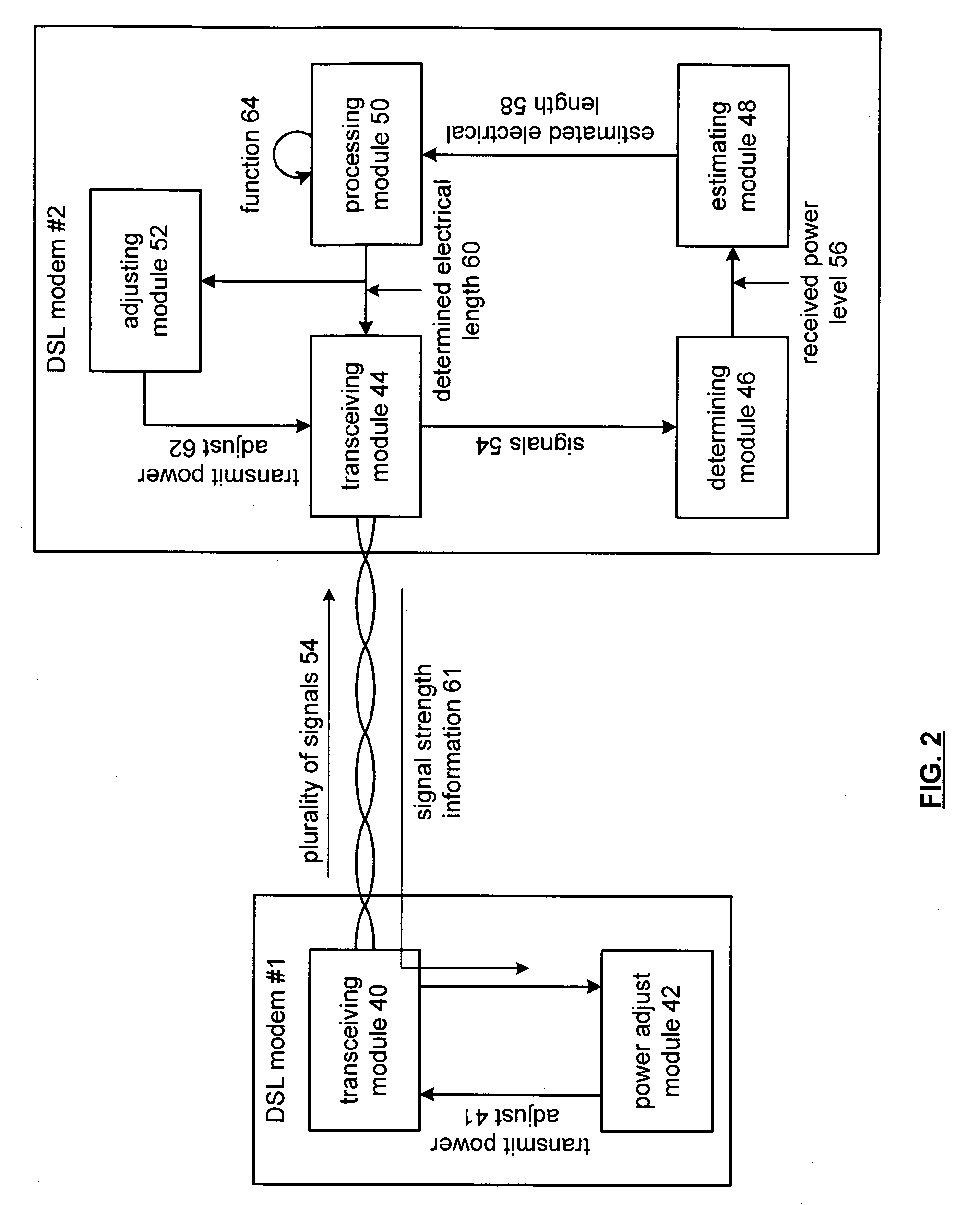
The present invention relates to a method for adjusting transmit power in a DSL network based on the estimated electrical length of a loop. The technical effect of this invention is to improve the quality of DSL communications by reducing far-end cross-talk, which occurs when signals transmitted from one modem interfere with signals transmitted from another modem in a multi-pair cable. By estimating the electrical length of the loop and adjusting transmit power accordingly, a more accurate estimate of the electrical length is obtained, resulting in a more efficient use of transmit power and improved DSL communications.

Problems solved by technology

Due to the usage of multiple pair cables, the length of the DSL loop is limited by mutual interferences between the pairs of wires within the same cable.
This interference is generally known as cross-talk, which causes errors in the received signal and thus reduces performance of the DSL modem.
In either of these methods for estimating the electrical loop length, errors result in an over estimation of the loop length.
Such errors occur because the loop length estimation method does not take into account inaccurate terminations at the end of the wires, mixed wire gauges, bridge taps (unloaded wire drops from the loop for another customer premises) water penetration, improper splicing, et cetera.
When the loop length is over estimated, the transmit power is not sufficiently reduced, thus the far end cross-talk is too large and continues to adversely affect the performance of the other DSL modems of the CO in the multi-pair cable.

Method used


Image

  • Transmit power adjustment based on estimated electrical length of a loop
  • Transmit power adjustment based on estimated electrical length of a loop
  • Transmit power adjustment based on estimated electrical length of a loop

Examples


Embodiment Construction

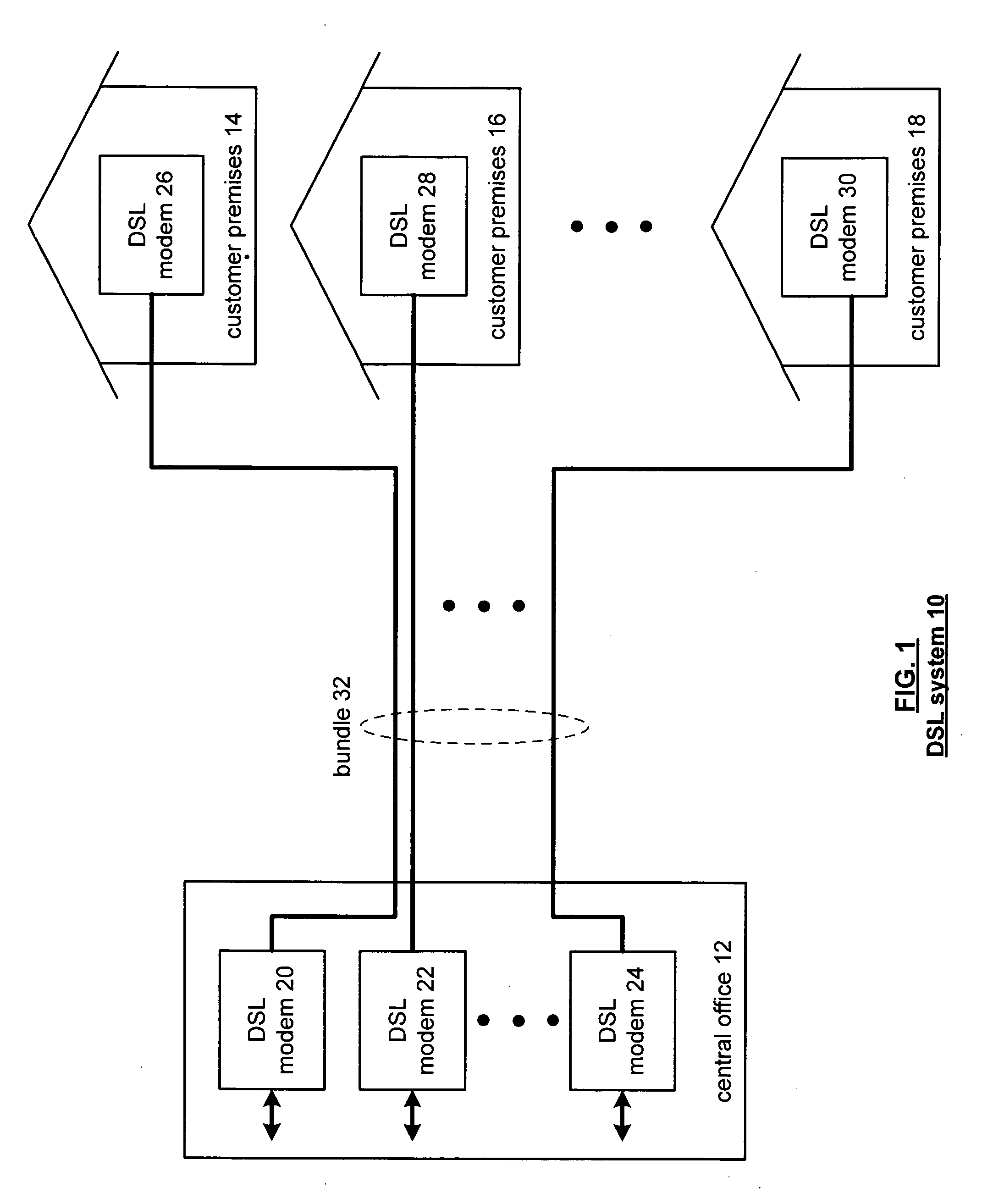
[0026]FIG. 1 illustrates a DSL system 10 that includes a central office 12 and a plurality of customer premises 14-18. The central office 12 includes a plurality of DSL. modems 20-24. Each of the customer premises includes a DSL modem 26-30. Each DSL modem 26-30 at a customer premises 14-18 is coupled via a twisted pair of wires with a corresponding DSL modem 20-24 in the central office. The twisted pairs between the central office 12 and the plurality of customer premises 14-18 are bundled 32 to produce a multi-pair cable. As is known, a byproduct of the bundling 32 of the twisted wire pairs results in cross-talk interference between the twisted pairs that reduces the performance of the overall DSL system 10.

[0027] As one of average skill in the art will appreciate, the DSL system 10 may include multiple central offices and many more customer premises than shown in FIG. 1. For DSL systems that include multiple central offices, the central offices are tied together through a commun...


PUM


Abstract

A method for estimating electrical length of a loop in a digital subscriber line (DSL) system begins by estimating an electrical length of a loop for each of a plurality signals based on a known power level of the plurality of signals, a known frequency for each of the plurality of signals, and a received power level for each of the plurality of signals. The method continues by processing the plurality of estimated electrical lengths in accordance with a function corresponding to characteristics of the loop to produce a determined electrical length.

Description

[0001] This patent application is claiming priority under 35 USC § 120 as a continuing patent application of co-pending patent application entitled ADJUSTMENT OF TRANSMIT POWER BASED ON AN ESTIMATED ELECTRICAL LENGTH OF A LOOP, having a filing date of Jul. 23, 2002, and a Ser. No. 10 / 201,129.BACKGROUND OF THE INVENTION [0002] 1. Technical Field of the Invention [0003] This invention relates generally to communication systems and more particularly to Digital Subscriber Line (DSL) based communication systems. [0004] 2. Description of Related Art [0005] Communication systems are known to enable a plurality of communication devices to communicate among themselves and with communication devices in other communication systems. Such communication devices, which may be computers, modems, facsimile machines, printers, personal digital assistants, et cetera, communicate voice, text, and / or video data. Such communication systems support the communication of data in accordance with one or more ...

Claims


Application Information

Patent Timeline
Patent Type & Authority Applications(United States)
IPC IPC(8): H04B1/38H04L12/66
CPCH04L12/66
Inventor OKSMAN, VLADIMIRRAHAMIM, RAPHAEL
Owner AVAGO TECH INT SALES PTE LTD
Learn More