Image recording apparatus

Inactive Publication Date: 2006-09-14
OKI DATA CORP
View PDF8 Cites 19 Cited by
  • Summary
  • Abstract
  • Description
  • Claims
  • Application Information

AI Technical Summary

Benefits of technology

[0014] With such an image recording apparatus according to the present invention, the divisional rate for dividing the heat amount charged per unit time by means of the plural heater members having different heat distribution can be set variably according to the temperature difference of the areas where the print medium passes through, such that the temperature difference occurring between the end portions and the central portion of the print medium can be minimized, resulting in prevention of the fusing nonuniformity.
[0015] Since the image recording apparatus according to the present invention detects the fusing conditions based on the temperature difference of

Problems solved by technology

However, in this type of image recording apparatus, a temperature of an area of the fusing roller where the printing paper does not pass therethrough becomes higher than a temperature of an area of the fusing roller where the printing paper passes therethrough in a case where a width of the printing paper is shorter than a width of the fusing roller, resulting in the fusing nonuniformity at end portions of the printing paper.
However, in the conventional fusing device as stated in the above Japanese Patent Laying-Open Publication No. 2001-201978, if fusing is attempted to be performed onto printing papers of various widths such as a range of sizes of A5 lengthwise size to A3 lengthwise extended size, only a switching of a use of two heaters between a large size and a small size often raises a problem of an occurrence of the

Method used


Image

  • Image recording apparatus
  • Image recording apparatus
  • Image recording apparatus

Examples


Example

[0047] Explained here is the printer as the first embodiment.

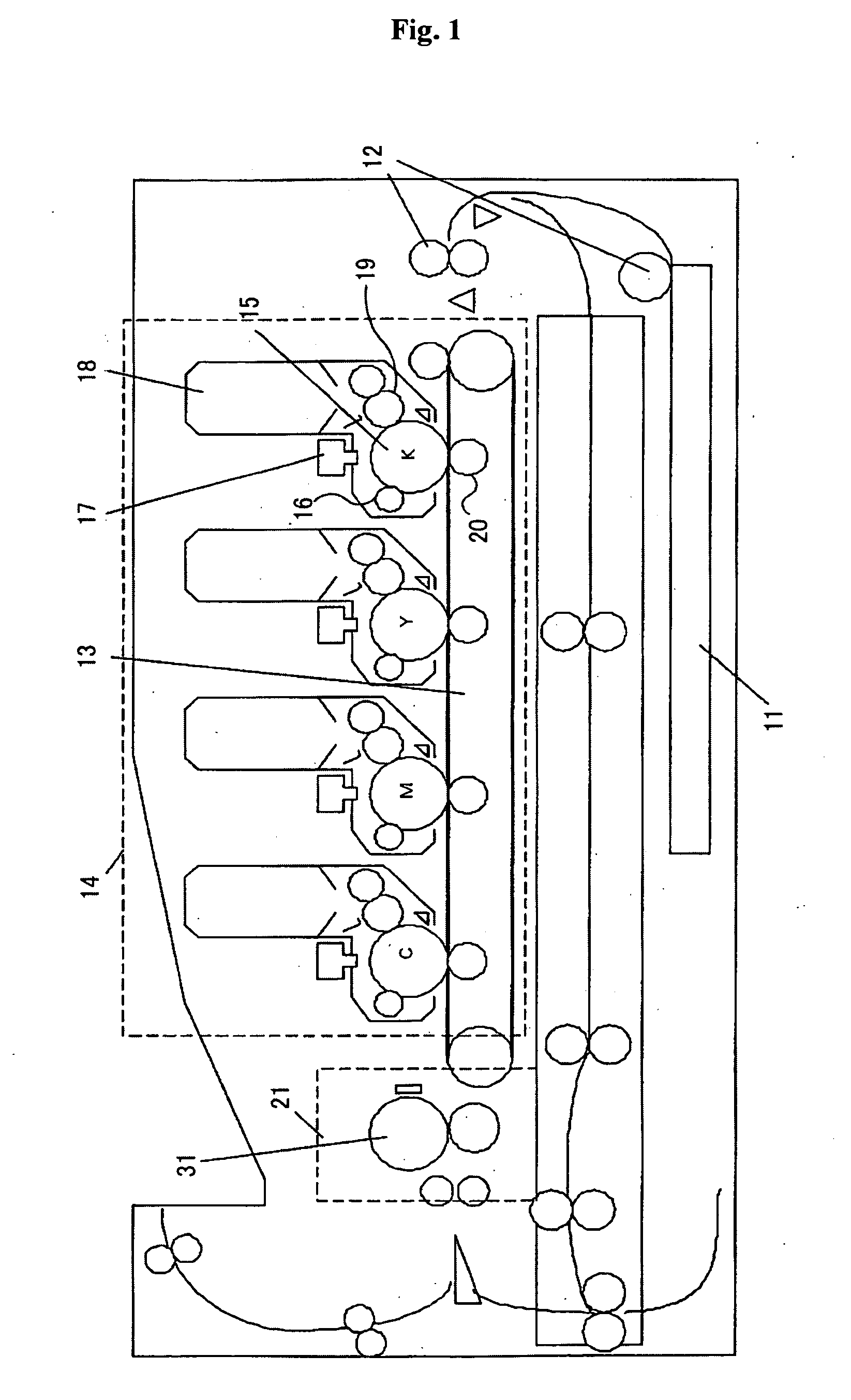
[0048]FIG. 1 is a laterally cross sectional view illustrating a printer configuration. This printer has sheet stacker 11 for stacking printing papers as unprinted print media. The printing papers stacked in sheet stacker 11 is supplied from sheet stacker 11 in cooperation with a rotation of conveyer roller 12 disposed in a front portion of the printer to be conveyed to transfer belt 13 rotated by a motor, not shown, at a rotation speed suitable for printing speed.

[0049] Also, the printer has image printing section 14 in which four image printing units corresponding to four colors of black (K), yellow (Y), magenta (M) and cyan (C) are disposed in parallel in this order from a supplying side to a discharging side of the print media. Each image printing unit performs image formation onto the printing paper placed on transfer belt 13 using each color of toner. More specifically, the each of the image printing units includes ...

Example

[0089] Explained next is a printer exemplified as a second embodiment.

[0090] The printer as the second embodiment has a temperature sensor for detecting the temperature of the end portion in the axis direction of the fusing roller. Therefore, in the explanation of the second embodiment, the same numerals and / or symbols are assigned to the elements similar to those in the first embodiment and therefore omit the detailed explanations thereof.

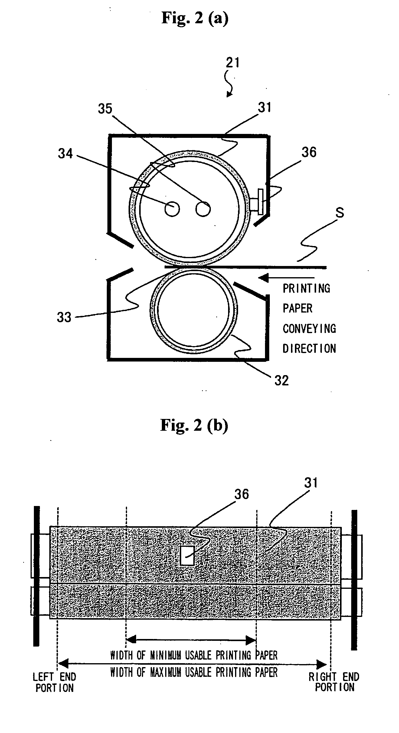
[0091] Fusing unit 21 of the printer according to the second embodiment is provided with end portion temperature sensor 101 on a surface of the end portion in the axis direction of fusing roller 31 in a surface contacting manner as shown in FIG. 13. Fusing unit 21 detects the surface temperature of the end portion in the axis direction of fusing roller 31 by using end portion temperature sensor 101.

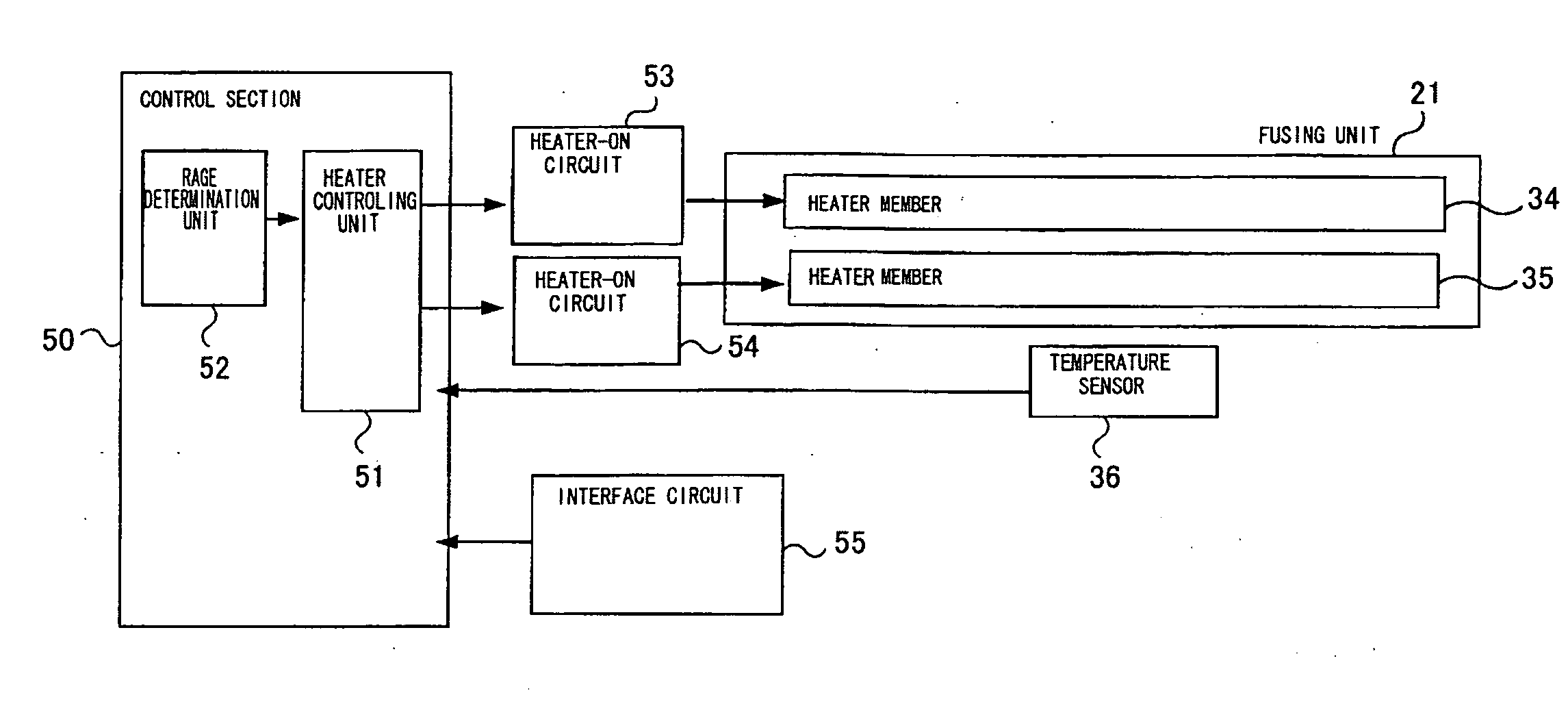
[0092] The above stated fusing unit 21 heat controls heater members 34, 35 according to the control system as shown in FIG. 14. That is, apart from ...


PUM


Abstract

A purpose of the present invention is to minimize a temperature difference between end portions and a central portion of a print medium caused by a difference of fusing conditions.
The image recording apparatus according to the present invention includes a plurality of heater members 34, 35 having different heat distributions, a temperature detecting unit 36 for detecting a temperature of an area where a print medium passes through, a heat controlling unit 51 for controlling a fusing unit at a prescribed temperature by an individual heat controlling of the plurality of heater members on the basis of the temperature detected by the temperature detecting unit, a rate determination unit 52 for determining a divisional rate of heat amount to be charged per unit time to said fusing unit by means of said plurality of heater members. The rate determination unit determines the divisional rate of the heat amount to be charged per unit time to the fusing unit by means of the plurality of heater members on the basis of the fusing conditions input through a condition input unit and the heat controlling unit heat controls the plurality of heater members individually on the basis of the divisional rate determined by the rate determination unit.

Description

BACKGROUND OF THE INVENTION [0001] 1. Field of the Invention [0002] The present invention relates to an image recording apparatus which applies heat and pressure to a predetermined print medium to heat fuse a toner image onto the print medium. [0003] 2. Description of Related Art [0004] Conventionally, an electrophotographic recording type image recording apparatus for forming an image by heat fusing a toner image onto a predetermined print medium has been known. Such an image recording apparatus includes processes of charging and exposing a photo conductor, developing an electrostatic latent image formed on the photo conductor by a toner, transferring of thus obtained toner image onto the print medium and fusing the toner image onto the print medium, resulting in a formation of an image. [0005] In this type of image recording apparatus, a constant control of a temperature of a fusing roller when a printing paper as the print medium passes therethrough improves a prevention of a fus...

Claims


Application Information

Patent Timeline
IPC IPC(8): G03G15/20
CPCG03G2215/2016G03G2215/2032G03G15/2042
Inventor WATABE, TOMONORI
Owner OKI DATA CORP
Why Eureka
Try Eureka