Binder for filing tool

Active Publication Date: 2006-09-14
KING JIM CO LTD
View PDF4 Cites 1 Cited by
  • Summary
  • Abstract
  • Description
  • Claims
  • Application Information

AI Technical Summary

Benefits of technology

[0008] The present invention is a binder for filing tools which binds sheets having a plurality of sheet hole parts aligned in the center, comprising a locking bar which corresponds to a front cover wherein two front cover parts formed from flat boards of which one side of each is respectively connected to a back cover part and integrated, wherein the sheets are placed such as to be held between the locking bar and the front cover and filing suitable for the number of sheets to be bound is possible by comprising a space setting means for setting the distance between the locking bar and the front cover.
[0013] Here, by using the band-shaped back board, disassembly and separation of articles are facilitated and environmental measures subsequent to use is facilitated.
[0018] Here, although the length of the locking groove is arbitrary, by making the width of the groove narrower and the depth shallower, the closer it is to the connected circular part, the more smoothly the key part can move within the locking groove.
[0026] The joining groove and the joining groove bottom part of the locking bar are carved at an acute angle in accordance to the key-shaped locking part of the engaging band-shaped back board. The engagement becomes stronger by carving at an acute angle.
[0034] The locking bar is composed of a flexible locking bar which has flexibility.

Problems solved by technology

On the other hand, as the number of parts increase, attachment and removal becomes less than easy, and its structure is not necessarily simple.
However, because a folding-type band-shaped component folded from the top and bottom of the file, is used, there are problems in that exterior deterioration of the folding sections, such as whitening, occurs more easily and it weakens in terms of strength, as well.

Method used


Image

  • Binder for filing tool
  • Binder for filing tool
  • Binder for filing tool

Examples


first embodiment

[0059] the present invention is described in detail hereafter, with reference to the drawings.

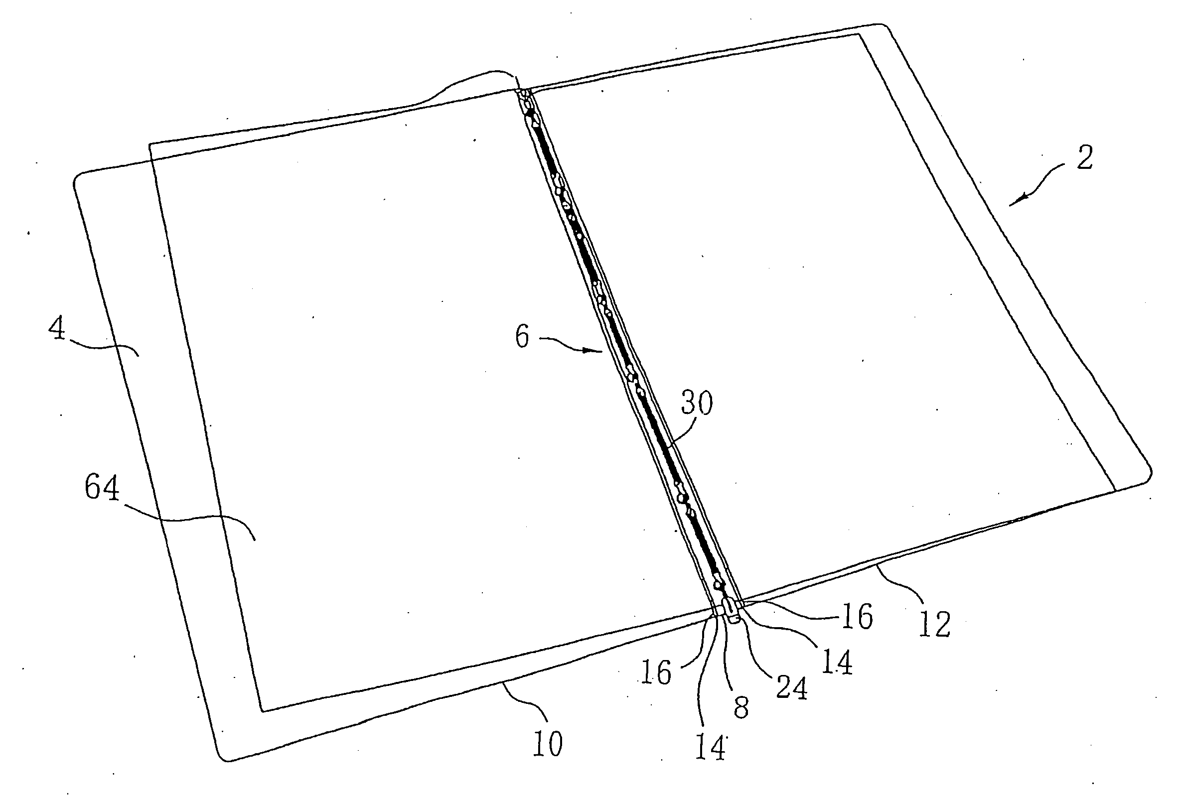
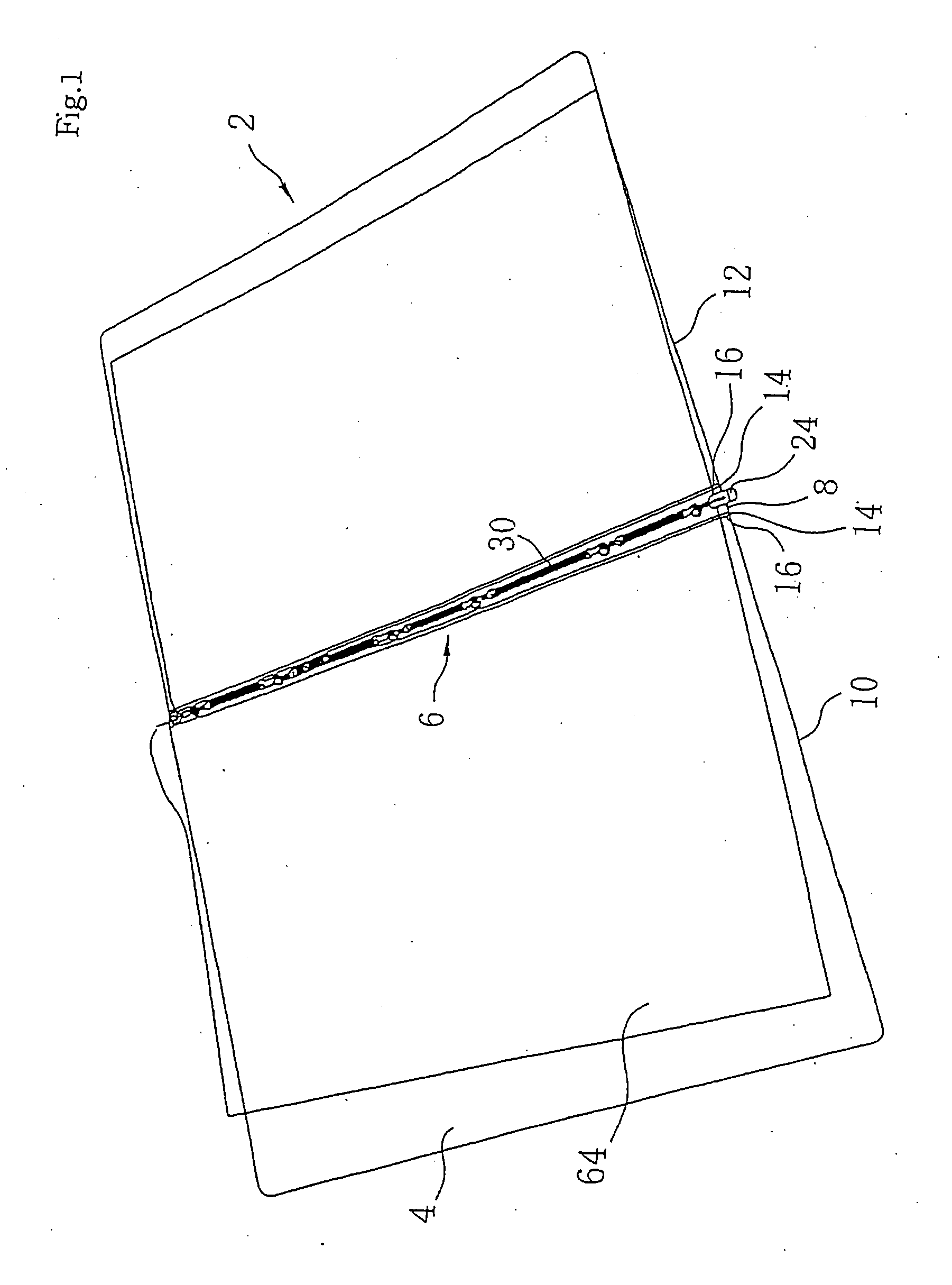
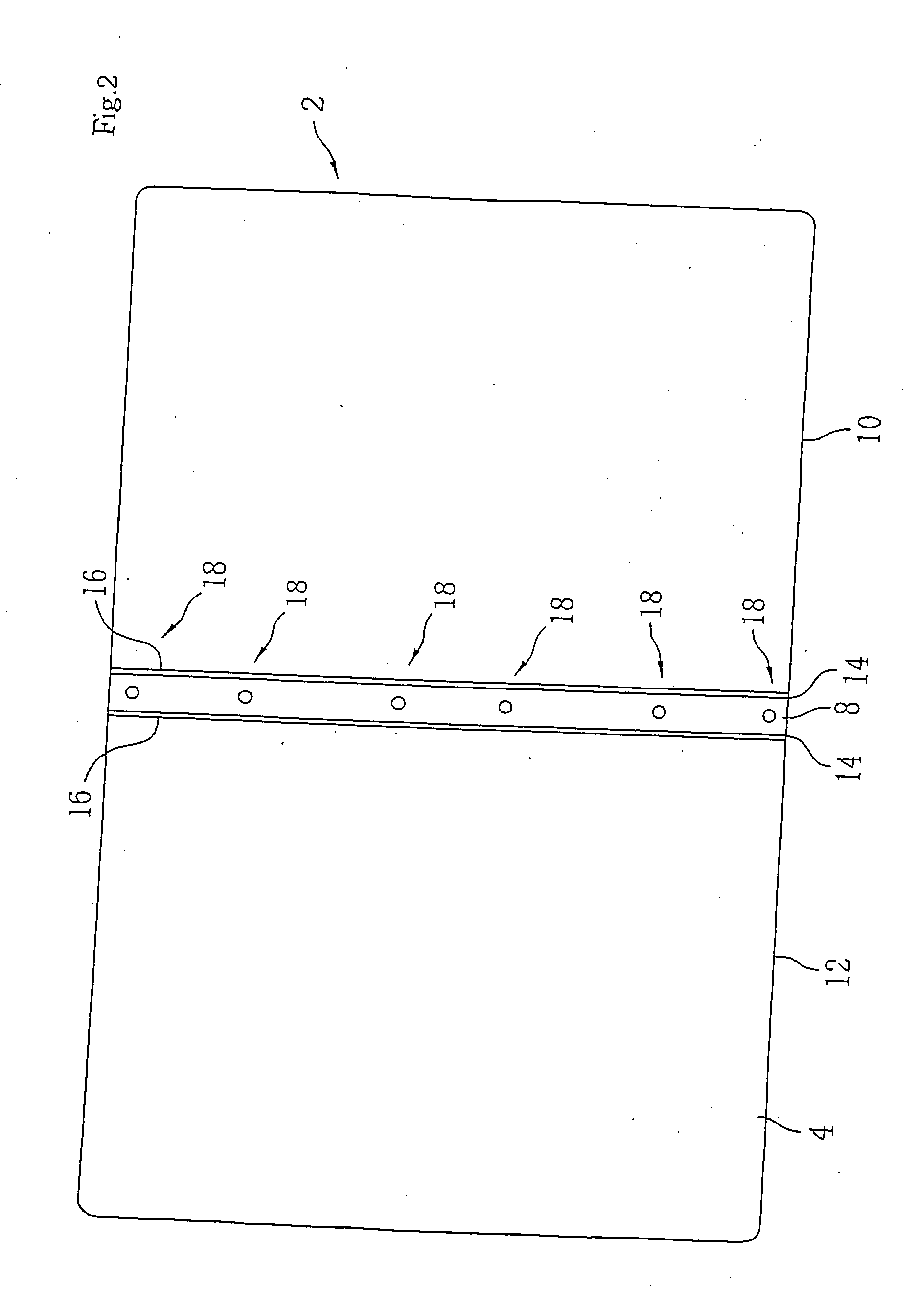
[0060] File 2 comprises a file main unit 4 and a binder for filing tools 6, as shown in FIG. 1. The file main unit 4 and the binder for filing tools 6 are synthetic resin moldings, and integral molding has been performed on the file main unit by extrusion molding or injection molding and on the binder for filing tools by injection molding or the like. File main unit 4 comprises a vertically long rectangular back cover part 8 and a pair of vertically long rectangular front cover parts 10 and 12 which are connected with the back cover part 8 in between, on both sides of its long side. As shown in FIG. 2, a first hinge 14 which is formed from a V-shaped groove wherein the thickness becomes thin due to the thickness of file main unit 4 is formed on the border of the back cover part 8 and the front cover parts 10 and 12, and the front cover parts 10 and 12 can be folded easily, due to this first...

second embodiment

[0090] the binder for filing tools of the present invention is shown in FIG. 17 to FIG. 19.

[0091]FIG. 17(a) is a rear view of a locking bar 100, (b) is a front view of the locking bar 100, (c) is an A-A′ line cross-sectional view. Ribbing 102 are formed to protrude respectively from the outer four side edge parts of the rectangular locking bar 100 outwards and perpendicular to the rear surface 105 which is one of the surfaces. A plurality of hole parts 103 are formed to protrude from predetermined positions along the long axis direction of the locking bar 100, on the rear surface 105 of the locking bar 100. The hole parts 103 are formed in a state wherein the release diameter hole part 104 having a large diameter and a lock diameter hole part 106 having a small diameter are partially overlapping. A tying part 109 which has a width Y smaller than either diameter is provided in the joining part of this release diameter hole part 104 and lock diameter hole part 106. Deflection clearanc...

third embodiment

[0102] the binder for filing tools of the present invention is shown in FIG. 20.

[0103]FIG. 20 (a) is a front view of a locking bar 140. A hook hole part 142 is formed to protrude from one edge of the locking bar 140. A stopper 156 which is slightly wider than the locking bar 140 is provided on the other edge. FIG. 20 (b) is an A-A′ line cross-sectional view. The cross-section of the locking bar 140 is a semi-circle and comprised of a curved surface 114 and a flat surface 146. FIG. 20 (c) is a side view of a band-shaped back board 148. Protruding parts 150 are formed on bottom board part 152 to protrude perpendicular to the bottom board part 152 with a predetermined distance in between. Circular hole parts 154 are drilled parallel to the long axis direction of the bottom board part 152 on the upper part of the protruding part 150. A hook part 160 is formed to protrude parallel to the protrusion part 150 on one edge part of the bottom board part 152. This hook part 160 is inserted int...


PUM


Abstract

A binder for filing tools which binds sheets having a plurality of sheet hole parts aligned in the center includes a locking bar which corresponds to a front cover wherein two front cover parts formed from flat boards of which one side of each is respectively connected to a back cover part and integrated. The back cover part includes a plurality of key-shaped locking parts erected on the front surface thereof, the key-shaped locking part is penetrated through the sheet hole parts in the sheet, a plurality of tying parts are provided in the locking bar in positions corresponding to the positions of the key-shaped locking parts, and the sheets are held between the locking bar and front cover by each tying part being locked to the key-shaped locking part.

Description

TECHNICAL FIELD [0001] The present invention relates to a file and, more particularly, a file which is a binder for facilitating the attachment and removal of a sheet having binding holes, wherein binding of the holes as well as disassembly into respective parts are facilitated. BACKGROUND ART [0002] As conventional files, for example, a file which has a binding string coated with synthetic resin with flexibility but little expandability and a double row of ribbing erected on the upper surface of a band-shaped board (Japanese Utility Model Laid-Open Publication No. 62-162070), a file comprising a box unit with a cut out for drawers and a bottom plate having a receiving part for fitting, a pressing tool with a U-shaped cross-section, and a stopper tool with a protrusion part for fitting which is fitted onto the receiving part for fitting of the box unit (Japanese Utility Model Laid-Open Publication No. 54-151420), and a file composed of a file front cover, and a band-shaped component...

Claims


Application Information

Patent Timeline
IPC IPC(8): B42F13/00A44B99/00B42B5/08B42F13/14
CPCB42B5/08B42F13/14Y10T24/4406Y10T24/20Y10T24/44051Y10T24/44043B42F13/06B42F13/00
Inventor SHIMADA, HIROSHITODA, NAOTOSHIYATABE, TOMOHIRO
Owner KING JIM CO LTD
Why Eureka
Try Eureka