Water resistant slide fastener
- Summary
- Abstract
- Description
- Claims
- Application Information
AI Technical Summary
Benefits of technology
Problems solved by technology
Method used
Image

Examples
first embodiment
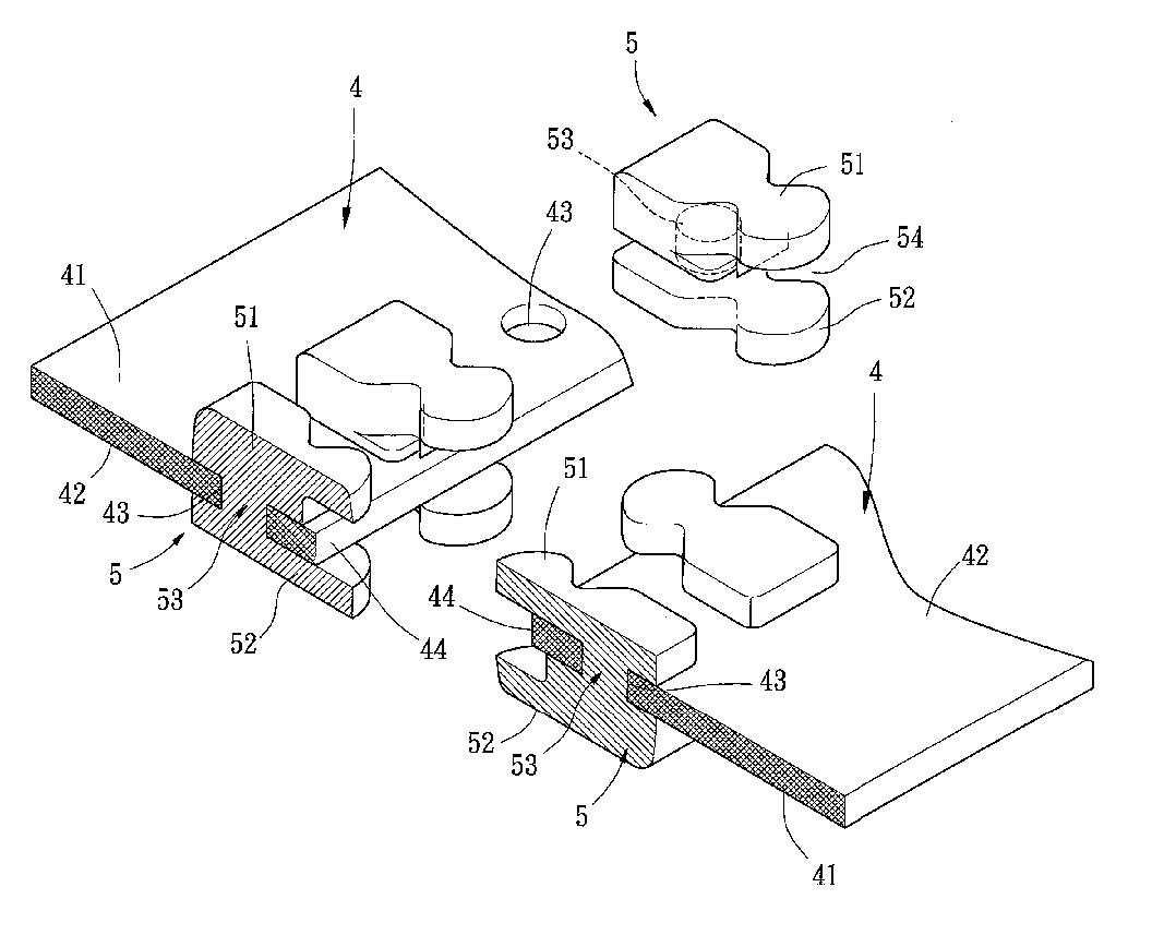
[0033] Referring to FIG. 5 through 7, a water resistant slide fastener in accordance with the present invention comprises two supporting members 4 and a row of coupling elements 5 longitudinally provided on each supporting member 4. The supporting members 4 are made of a water resistant material preferably selected from a group consisting of rubber, plastics, and resins to form a flexible structure. Each supporting member 4 includes a first surface 41, a second surface 42 opposite to the first surface 41, and a longitudinal edge 44.
[0034] A row of coupling elements 5 is formed on a longitudinal side of a supporting member 4 for engaging with the other row of coupling elements 5 on the other supporting member 4. More specifically, a portion of each coupling element 5 is formed on the first surface 41 of an associated supporting member 4, forming a first portion 51 of each coupling member 5. Another portion of each coupling element 5 is formed on the second surface 42 of the associate...
second embodiment
[0038]FIG. 10 illustrates the invention. In this embodiment, the supporting members 6 are made of a non-water-resistant material such as polyester fiber cloth. In the illustrated embodiment, the supporting members 6 are made of conventional cloth. A water resistant layer 65 is provided on at least one of the first surface 61 and the second surface 62 of each supporting member 6. The water resistant layer 65 is made of water resistant resin or polyurethane and applied to the supporting member 6. If necessary, the water resistant layer 65 extends to the longitudinal edge 64 of each supporting member 6. When the coupling elements 5 of the supporting members 6 are engaged with each other, the longitudinal edges 64 of the supporting members 6 overlap each other, as shown in FIG. 11. An excellent waterproof effect is thus provided.
third embodiment
[0039]FIGS. 12 and 13 illustrate the invention. In this embodiment, the supporting members 7 are flexible and made of rubber, plastics or resins. Alternatively, the supporting members 7 are made of non-water-resistant material and include a water resistant layer on at least one surface thereof. A row of coupling elements 5 is formed on a longitudinal side of each supporting member 7. Each coupling element 5 includes a first portion 51 on a first surface 71 of an associated supporting member 7, a second portion 52 on a second surface 72 of the associated supporting member 7, and a connecting portion 53 between the first portion 51 and the second portion 52. Each supporting member 7 includes a plurality of through-holes 73 through which the connecting portions 53 of the coupling elements 5 extend, allowing firm bonding between the coupling elements 5 and the supporting member 7. The longitudinal edge 74 of each supporting member 7 extends into the gaps 54 defined between the first por...
PUM
 Abstract
Description
Claims
Application Information
 - Generate Ideas
- Intellectual Property
- Life Sciences
- Materials
- Tech Scout
- Unparalleled Data Quality
- Higher Quality Content
- 60% Fewer Hallucinations
Browse by: Latest US Patents, China's latest patents, Technical Efficacy Thesaurus, Application Domain, Technology Topic, Popular Technical Reports.
© 2025 PatSnap. All rights reserved.Legal|Privacy policy|Modern Slavery Act Transparency Statement|Sitemap|About US| Contact US: help@patsnap.com