Surgical depth instrument

a technology of depth gauge and surgical device, which is applied in the field of instruments, can solve problems such as paralysis, damage to the fat layer of the finger, and difficulty in adjusting the depth gauge, and achieve the effects of improving accuracy, reducing pain, and improving accuracy

Active Publication Date: 2006-09-21
EDGE SURGICAL INC
View PDF9 Cites 58 Cited by
  • Summary
  • Abstract
  • Description
  • Claims
  • Application Information

AI Technical Summary

Problems solved by technology

That is, the opposite side of the bone from the drill site will typically be abutted by soft tissues that may be harmed if the screw is too long.
As an example, a fastener mounted in the pedicle portion of the human spine should not extend to a point where the fastener contacts the spinal cord itself, an event that can cause irreparable nervous system damage including paralysis.
Over-drilling through a metacarpal may simply result in damage to the fat layer within the finger.
However, if a screw is used that is too long, it may protrude and be tactilely felt by the patient, or it may pierce the skin itself.
A number of problems are experienced with this depth gauge.
Therefore, the brightness of the operating room lights on the highly reflective surface can make the markings difficult to read.
The markings are commonly in small increments, such as millimeters, and surgeons often have trouble differentiating between the markings, or noting partial increments.
Reading these gauges, then, often requires carefully holding the depth gauge as the reading is taken, and a surgeon's effort to closely examine the reading ma

Method used


Image

  • Surgical depth instrument
  • Surgical depth instrument
  • Surgical depth instrument

Examples


Embodiment Construction

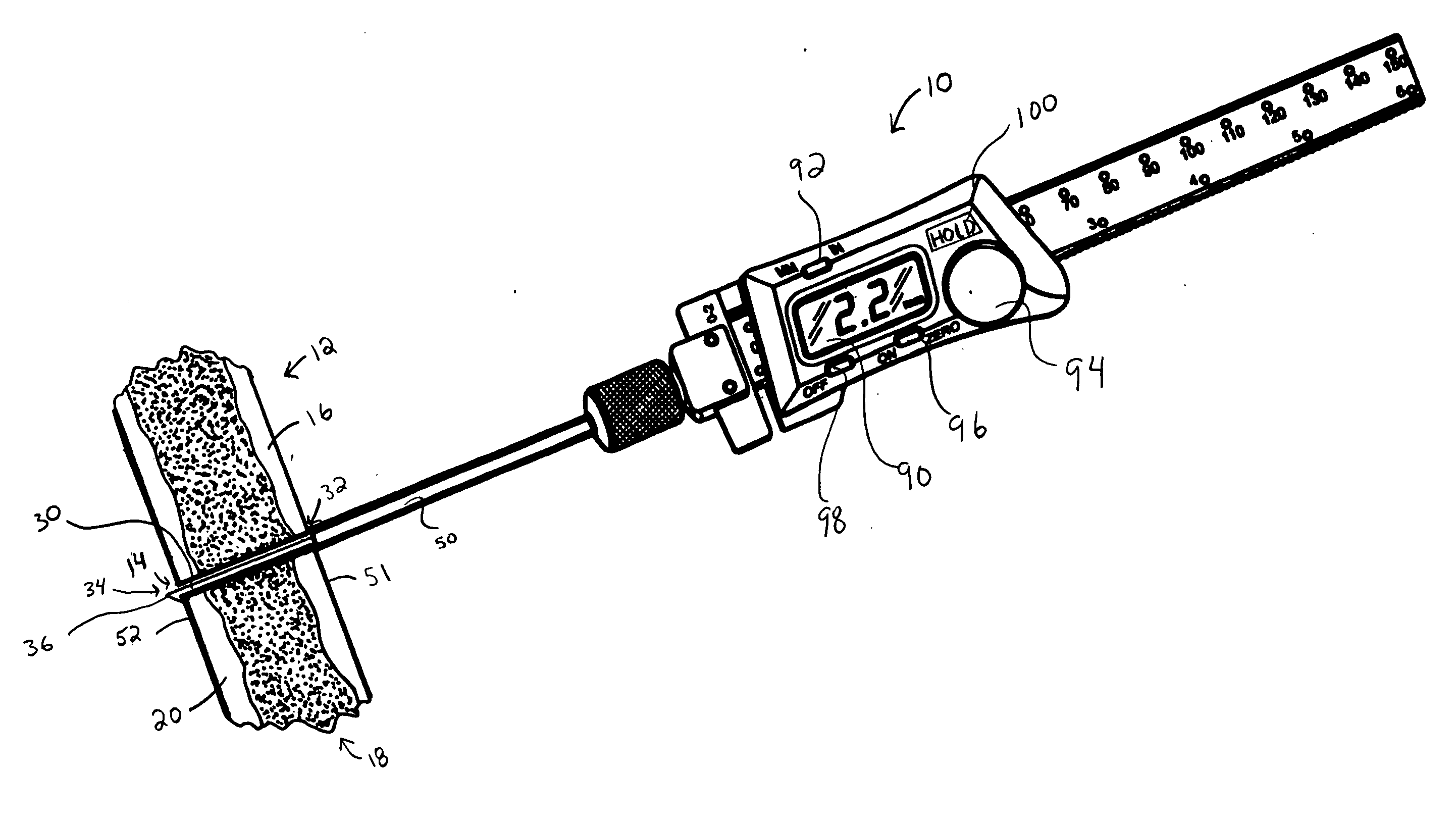
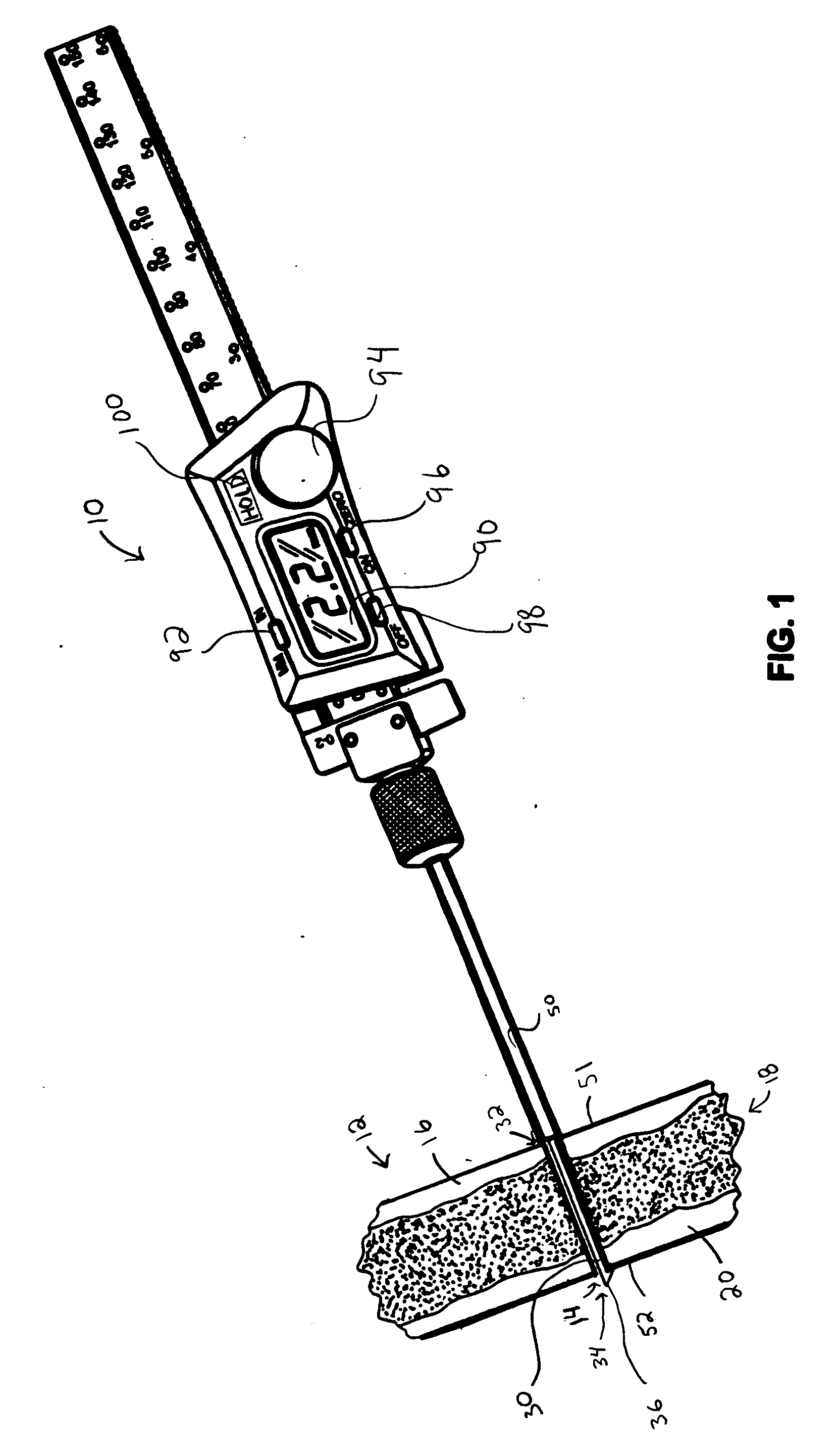
[0016] Referring initially to FIG. 1, a depth instrument 10 is depicted secured with a bone portion 12 in order to measure the depth of a passageway in the form of a bore or hole 14 formed therein for receiving a fastener such as a screw (not shown). As can be seen, the bone portion 12 is bi-cortical. That is, the bone portion 12 has a first, proximal cortical layer 16, a cancellous layer 18, and a second, distal cortical layer 20. However, it should be noted that the instrument 10 is suitable for use with bone portions having other structures, such as those including solid cortical bone.

[0017] As described above, the hole 14 may be a pilot hole formed in the bone portion 14. In using the instrument 10 to measure the distance from a proximal surface 51 formed on the proximal cortical layer 16 to a distal surface 52 formed on the distal cortical layer 20, the instrument 10 operates such that the relative movement between two portions respectively abutting the proximal surface 51 and...


PUM


Abstract

A depth gauge for measuring the depth of a hole in a bone is disclosed having a digital readout for providing the measurement to a surgeon. The depth gauge has a probe with a tip inserted into and positioned proximate to the depth the hole, and has a reference member adjustably positioned relative the probe and against the bone proximate the hole. A measuring device is provided with the depth gauge for measuring the relative distance between the tip and the reference member, and the measuring device has a large, digital display for providing the relative distance.

Description

FIELD OF THE INVENTION [0001] The invention relates to an instrument for determining the depth of a hole and, in particular, a depth gauge for providing a digital measurement of the depth of a hole in a bone. BACKGROUND OF THE INVENTION [0002] Many surgical procedures utilize surgical devices secured to the bone of a patient. In some instances, a bone plate may be utilized that spans and secures together one or more bones or pieces thereof. In other instances, a screw or other fastener may be fastened to a bone without another device, such as a screw used to secure a transplanted tendon. [0003] In many of these procedures, it is preferred to create a pilot hole in the bone prior to securing the fastener in the bone. Oftentimes, this preference arises from the importance of having a fastener that is inserted to a proper depth. That is, the opposite side of the bone from the drill site will typically be abutted by soft tissues that may be harmed if the screw is too long. As an example...

Claims


Application Information

Patent Timeline
IPC IPC(8): A61B5/103
CPCA61B5/1076A61B5/4504A61B19/46A61B2019/461G01B3/28A61B90/06A61B2090/061A61B17/00
Inventor KIM, JOHN Y.S.
Owner EDGE SURGICAL INC
Why Eureka
Try Eureka