Termite monitoring and bait station

Inactive Publication Date: 2006-09-21
PCT HLDG
View PDF51 Cites 29 Cited by
  • Summary
  • Abstract
  • Description
  • Claims
  • Application Information

AI Technical Summary

Benefits of technology

[0008] It is an object of the present invention to provide an inground

Problems solved by technology

Termites cause billions of dollars damage to objects such as building structures, agricultural crops and trees around the world.
However, in recent years, environmental concerns about the pesticides used have resulted in the proscribing

Method used


Image

  • Termite monitoring and bait station
  • Termite monitoring and bait station
  • Termite monitoring and bait station

Examples


Embodiment Construction

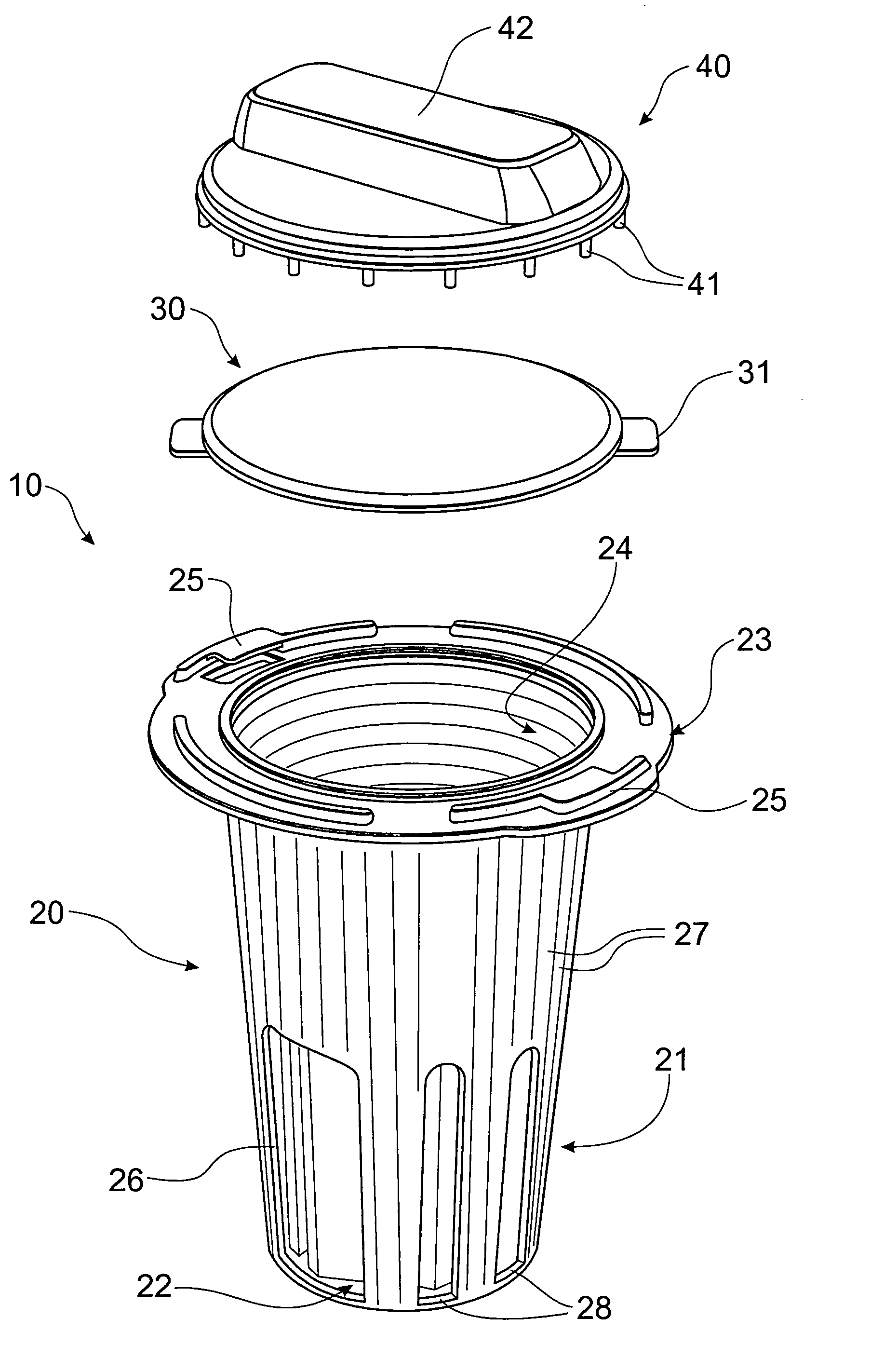
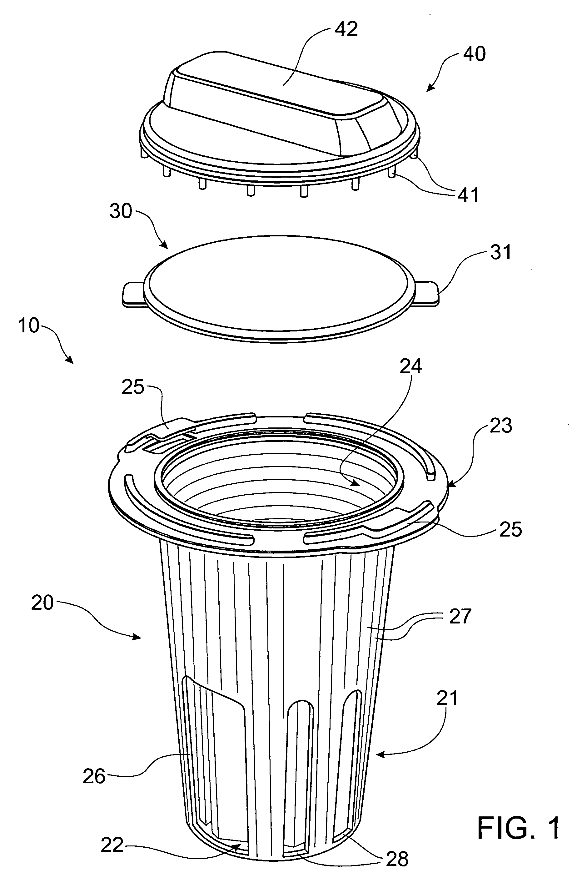
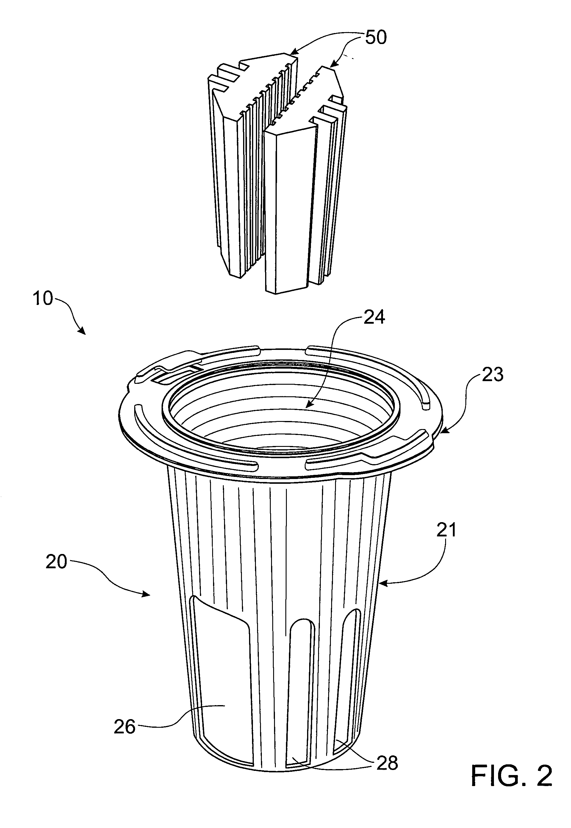
[0036] Referring to FIGS. 1 and 2, the termite monitoring station 10 has a housing 20, eg., injection moulded from plastics material, which is preferably termite-resistant.

[0037] The housing 20 has a frusto-conical side wall 21 (which is downwardly-convergent) and a bottom wall 22 (which may be provided with one or more holes, not shown).

[0038] A circumferential flange 23 is provided around the open “mouth” of the cavity 24 within the housing 20. A number of substantially vertical bracing flanges (not shown) may interconnect the circumferential flange 23 and the sidewall 21 to ensure stable, non-rotational, location of the housing 20 in a suitable hole formed in the soil (not shown).

[0039] A removable cover 30, also of plastics material, has a pair of diametrically-opposed locking flanges 31 for releasable engagement with complementary flanges 25, on the upper face of the circumferential flange 23, to provide a releasable bayonet-type connection between the removable cover 30 and...


PUM


Abstract

A termite monitoring and baiting station (10) has a housing (20), with a removable cover (30), defining a cavity (24) to receive one or more pieces of termite attractant material (50), eg., mountain ash. The termite attractant material (50) may partially extend outwardly through holes (26,28) in the side wall (21) of the container (20) and has grooves (53) to increase the effective surface area and to provide tracks for the termites. When termite activity is noted, a termite toxicant bait (60) is placed in the cavity (24), to enable the termites to carry the bait material (62) back to their colonies.

Description

BACKGROUND OF THE INVENTION [0001] 1. field of the Invention THIS INVENTION relates to a termite monitoring station. The invention also relates to a termite monitoring station in which bait may be inserted to suppress or eradicate colonies of termites. [0002] 2. Prior Art [0003] Termites cause billions of dollars damage to objects such as building structures, agricultural crops and trees around the world. [0004] For many years, termite control relied upon the use of environmentally-persistent pesticides at points of possible termite entry and attack. However, in recent years, environmental concerns about the pesticides used have resulted in the proscribing of such pesticides, at least in developed countries. [0005] One viable low-impact solution has been the adoption of termite baiting, where the termites are aggregated at a fixed point and are eliminated due to their consumption of a toxicant-containing bait placed at the point of aggregation. [0006] However, as the baits are expen...

Claims


Application Information

Patent Timeline
IPC IPC(8): A01M17/00A01M1/20
CPCA01M1/026A01M1/2005A01M1/2011A01M2200/011
Inventor PEARSON, DAVID
Owner PCT HLDG
Why Eureka
Try Eureka