Sealing system for refrigeration cassette

a refrigeration cassette and sealing system technology, applied in the field of refrigeration merchandisers, can solve the problems of increasing the workload of the evaporator, reducing the efficiency of the refrigeration operation, etc., and achieve the effect of facilitating the removal of the refrigeration unit cass

Inactive Publication Date: 2006-09-21
CARRIER CORP
View PDF29 Cites 15 Cited by
  • Summary
  • Abstract
  • Description
  • Claims
  • Application Information

AI Technical Summary

Benefits of technology

[0019] In an embodiment, the lower wall of the cabinet forms the common wall separating the refrigerated interior space and the equipment compartment wherein the refrigeration unit cassette is housed. In this embodiment, the positioning apparatus is a lifting apparatus for selectively raising and lowering the refrigeration unit cassette. The lifting apparatus may comprise a cam mechanism selectively positionable in a first position for positioning the refrigerated unit cassette into sealing relationship with the lower wall separating the refrigerated interior product space from an equipment compartment housing the refrigeration unit cassette, and is positionable in a second position for releasing the refrigerated unit cassette from its sealing relationship with the lower wall to facilitate removal of the refrigeration unit cassette from the equipment compartment.
[0020] In a one particular embodiment of the invention, the lifting apparatus is a pair of generally L-shaped members, one operatively associated with one side of the refrigeration unit cassette and the other operatively associated with the opposite side of the refrigeration unit cassette. Each generally L-shaped member has a first elongated leg extending along its respective side of the refrigeration unit cassette and includes at least one cam section therealong. The cam section may comprise a raised portion of the first leg. Each generally L-shaped member has a second leg outwardly from an end of the first leg in a second plane that is substantially perpendicular to a first plane in which the first leg and its raised portion lie. Each generally L-shaped member may be positioned in a first position for rotating the at least one cam section so as to raise the refrigeration unit cassette upwardly to compress the compressible seal between the refrigeration unit cassette and the lower wall thereby establishing the sealing relationship. Each generally L-shaped member may be positioned in a second position for rotating the at least one cam section so as to lower the refrigeration unit cassette downwardly to release the refrigeration unit cassette from sealing relationship with the lower wall. A flat surface may be provided on the surface of the raised portion of the first elongated leg contacting the refrigeration unit cassette when in the locked position.
[0021] In another embodiment of the invention, the lifting apparatus is a pair of cam sets, one set operatively associated with one side of the refrigeration unit cassette and the other operatively associated with the opposite side of the refrigeration unit cassette. Each cam set comprises at least two cam members disposed in spaced relationship and operatively interconnected by a linkage mechanism. Each linkage mechanism may be positioned in a first position for pivoting the cam members so as to raise the refrigeration unit cassette upwardly to compress the compressible seal between the refrigeration unit cassette and the lower wall thereby establishing the sealing relationship. Each linkage may be positioned in a second position for pivoting the cam members so as to lower the refrigeration unit cassette downwardly to release the refrigeration unit cassette from sealing relationship with the lower wall.

Problems solved by technology

Without an effective seal, return air could leak from the inlet duct to the outlet duct, thus bypassing the evaporator and reducing the efficiency of the refrigeration operation.
Additionally, air could leak into the return air duct from the ambient air stream passing into the condenser which would increase the workload on the evaporator.

Method used


Image

  • Sealing system for refrigeration cassette
  • Sealing system for refrigeration cassette
  • Sealing system for refrigeration cassette

Examples


Embodiment Construction

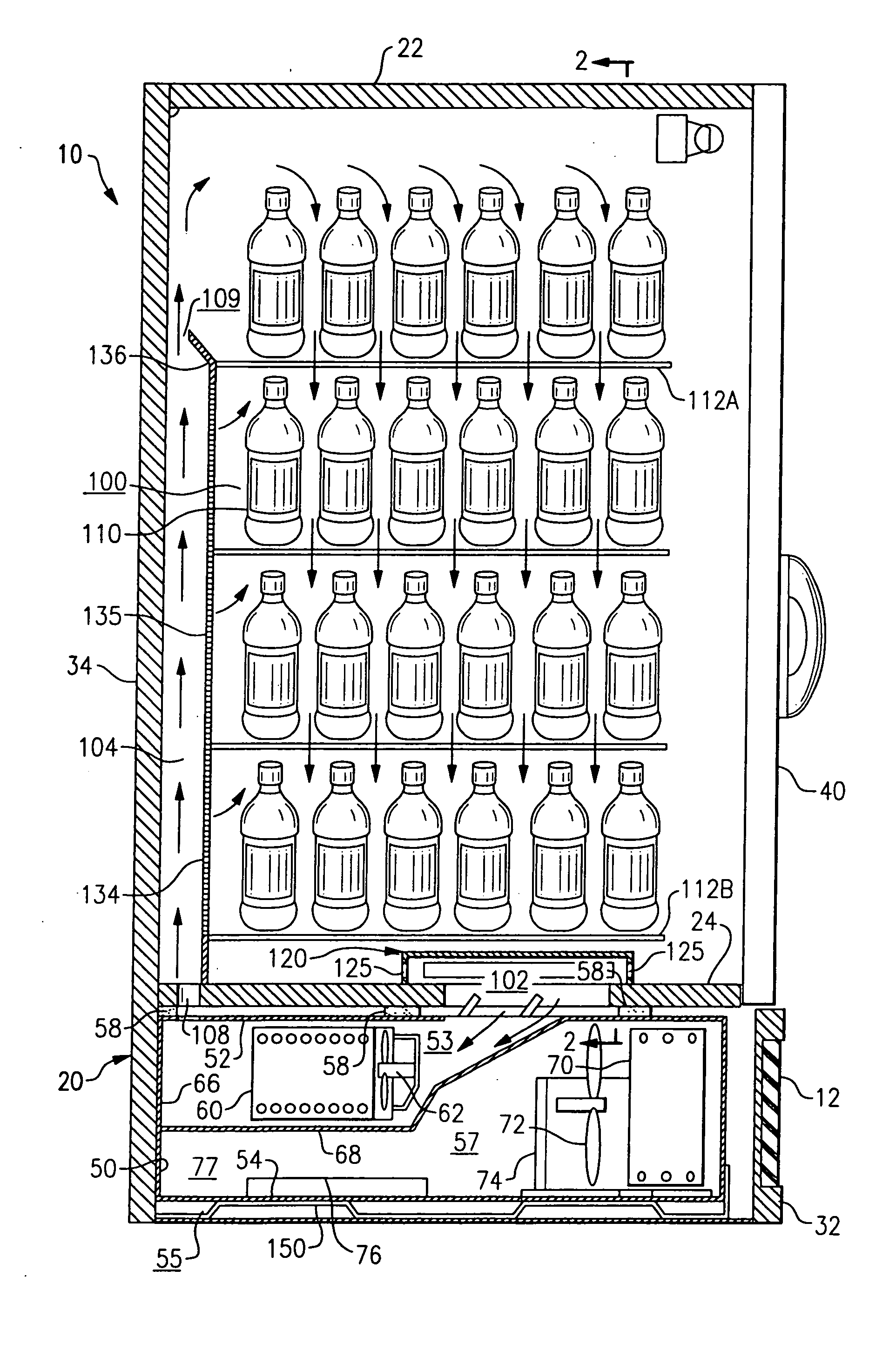
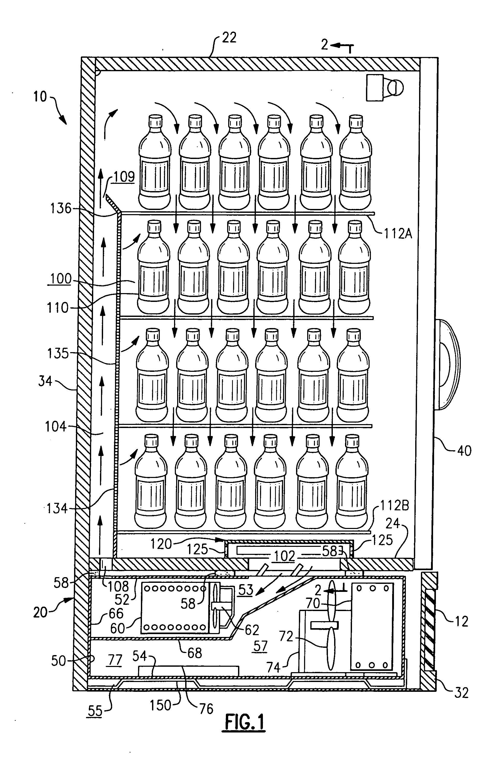
[0032] Referring now to FIGS. 1 and 2 in particular, there is depicted a refrigerated cold beverage merchandiser, designated generally by the reference numeral 10, including an interior product display space 100 for holding product 110 to be purchased, such as for example bottled or canned soda, milk, water, juices, fruit drinks, beer and other beverages. Although the invention will be described herein with reference to the depicted embodiment of a refrigerated cold beverage merchandiser, it is to be understood that that invention may be applied to other refrigerated display merchandisers for displaying perishable and frozen comestibles and beverages, including for example meats, poultry, fish, diary products, prepackaged frozen foods, and other products that need to be maintained in a controlled environment.

[0033] The beverage merchandiser 10 includes a cabinet 20 housing a refrigerated interior product display space 100 and a separate equipment compartment 55 disposed separate fr...


PUM


Abstract

A refrigerated merchandiser (10) includes a cabinet (20) having a top wall (22), a lower wall (24), a rear wall (34), and side walls (36, 38) defining an interior product display space (100) housing a product (110) in a refrigerated environment for consumer selection. A refrigeration unit (50) is disposed in operative association with the interior product display space in a compartment (55) beneath the lower wall (24). A first opening in the lower wall provides an air return inlet (102) establishing a flow passage from the interior product display space (1000 to the compartment (55) beneath the lower wall. A sealing member (58) is disposed between the under surface of the lower wall (24) and the upper surface of the refrigeration unit cassette (50) about the first opening; and a positioning apparatus (150) for raising the refrigeration unit cassette (50) unit into sealing relationship with the lower wall.

Description

CROSS REFERENCE TO RELATED APPLICATION [0001] This application claims the benefit of U.S. Provisional Application Ser. No. 60 / 662,960, filed Mar. 18, 2005, and entitled CAM COMPRESSION MECHANISM FOR GASKET SURFACES FOR REFRIGERATION CASSETTE AND CABINET DESIGNS, which application is incorporated herein in its entirety by reference. [0002] This application is related to the following applications subject to assignment to the common assignee of this application and filed with the United States Patent and Trademark Office on the same date as this application: [0003] U.S. patent application Ser. No. ______ (Attorney Docket No. 210—817NP), entitled “REFRIGERATED MERCHANDISER ”; [0004] U.S. patent application Ser. No. ______ (Attorney Docket No. 210—820NP), entitled “MODULAR REFRIGERATION CASSETTE ”; [0005] U.S. patent application Ser. No. ______ (Attorney Docket No. 210—879NP), entitled “MODULAR REFRIGERATION CASSETTE WITH CONDENSATE EVAPORATIVE TRAY ”; [0006] U.S. patent application Ser...

Claims


Application Information

Patent Timeline
Patent Type & Authority Applications(United States)
IPC IPC(8): A47F3/04F25D19/02
CPCA47F3/0408F25D19/02F25D2317/0651F25D2317/0661F25D2323/00264F25D2323/00276
Inventor DADDIS, EUGENE DUANE JR.AVILA, LUIS F.SAROKA, MARY D.KENNEY, STEPHENMEAD, BRIAN J.DANIELS, MARK A.
Owner CARRIER CORP
Why Eureka
Try Eureka