Auto entry guide

a technology for entry guides and muleshoes, applied in the direction of drilling casings, drilling pipes, borehole/well accessories, etc., can solve problems such as entering the receptacle, and achieve the effect of eliminating the eccentricity of the mulesho

Active Publication Date: 2006-09-21
BAKER HUGHES INC
View PDF14 Cites 15 Cited by
  • Summary
  • Abstract
  • Description
  • Claims
  • Application Information

AI Technical Summary

Benefits of technology

[0007] The invention provides systems and methods for guiding a seal assembly associated with a string of production tubing, or a tubular member generally, into a receptacle within a wellbore. In a described embodiment, the muleshoe of the seal assembly associated with the production tubing string is provided with an auto entry guide device in the form of a guide member or kickover lug that is radially moveable with respect to the muleshoe. The kickover lug is collapsible radially inwardly and biased radially outwardly. The biasing force is significant enough to cause the lug to urge the tip of the muleshoe into the receptacle. However, when the lug is collapsed radially inwardly, the eccentricity of the muleshoe is eliminated.
[0008] In a further described embodiment, the auto entry guide device includes a centralizer bowspring that is mounted upon the muleshoe. Additionally, the muleshoe is mounted for rotational movement with respect to the seal assembly. In operation, the presence of the bowspring tends to keep the extended tip of the muleshoe oriented toward the center of the wellbore, thereby causing it to enter the receptacle. This solution is effective when the wellbore is deviated.
[0009] Generally, the entry guide devices of the present invention do not require reciprocating or rotational movement in order to guide the muleshoe and allow proper seating. Rather, they operate automatically and typically require only downward movement to cause proper seating in a receptacle.

Problems solved by technology

In operation, the presence of the bowspring tends to keep the extended tip of the muleshoe oriented toward the center of the wellbore, thereby causing it to enter the receptacle.

Method used


Image

  • Auto entry guide
  • Auto entry guide
  • Auto entry guide

Examples


Embodiment Construction

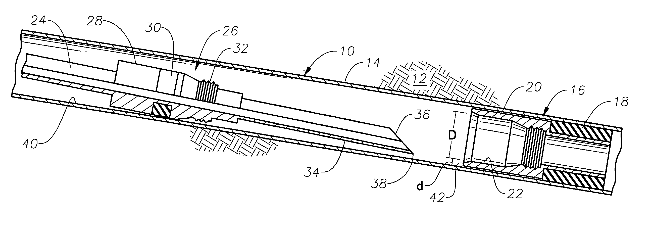
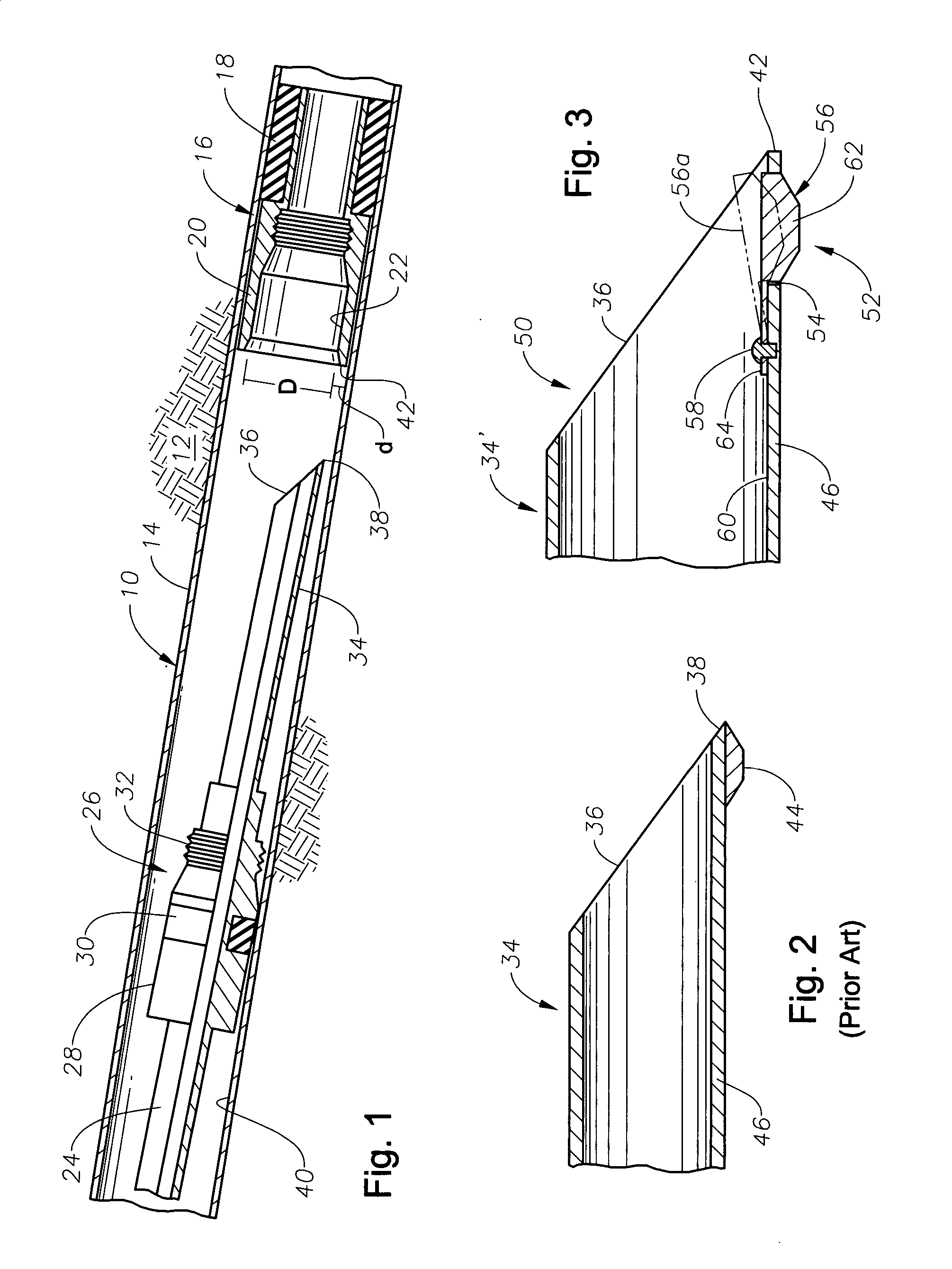
[0017]FIG. 1 illustrates a portion of a wellbore 10 that has been drilled generally downward through earth 12. As used herein, the terms “down,”“downward,”“lower,” and the like refer to positions within the wellbore that are further away, as measured from the well opening. The portion of wellbore 10 is deviated and, thus, runs at an angle that approaches the horizontal. The wellbore 10 contains casing 14 and a packer assembly 16 that has been previously secured to the casing 14 in a manner known in the art. The packer assembly 16 may surround a section of production tubing (not shown) that has been previously run in and secured within the wellbore 10.

[0018] The packer assembly 16 includes a packer element, shown schematically at 18, which is set against the casing 14. The packer element 18 supports an upper body portion 20 that presents a landing receptacle 22. The landing receptacle 22 also has an interior diameter (D) that is substantially coaxially located within the wellbore 10...


PUM


Abstract

Systems and methods for guiding a seal assembly associated with a string of production tubing, or a tubular member generally, into a receptacle within a wellbore. The muleshoe of a seal assembly is provided with an auto entry guide device in the form of a guide member or kickover lug that is radially moveable with respect to the muleshoe. The kickover lug is collapsible radially inwardly and biased radially outwardly. The auto entry guide device may also include a centralizer bowspring that is mounted upon the muleshoe. Additionally, the muleshoe is mounted for rotational movement with respect to the seal assembly.

Description

BACKGROUND OF THE INVENTION [0001] 1. Field of the Invention [0002] The invention relates generally to methods and devices for guiding landing tubular members, such as strings of production tubing, within a receptacle within a wellbore. [0003] 2. Description of the Related Art [0004] When sections of production tubing are run into a wellbore, they are often landed into a liner hanger or a packer to interconnect them with previously run sections of production tubing. A seal assembly is secured to the lower end of the production tubing string being run that will create a fluid seal with a receptacle in the packer or liner hanger. However, a problem associated with landing the seal assembly into the receptacle is that the entry to the receptacle is substantially-centered in the wellbore. If the wellbore is deviated, the seal assembly will tend to engage the edge of the receptacle instead of entering it. In order to correct the problem, it is often necessary to axially reciprocate and / o...

Claims


Application Information

Patent Timeline
Patent Type & Authority Applications(United States)
IPC IPC(8): E21B33/10
CPCE21B17/1028E21B33/04E21B33/10E21B47/09
Inventor CORBETT, THOMAS G.PETERSON, ELMER R.
Owner BAKER HUGHES INC
Why Eureka
Try Eureka