
Method and apparatus for measuring eccentricity of optical lens, and method and apparatus for centering and edging optical lens

Inactive Publication Date: 2006-05-16
ASAHI KOGAKU KOGYO KK
View PDF6 Cites 14 Cited by
  • Summary
  • Abstract
  • Description
  • Claims
  • Application Information

AI Technical Summary

Benefits of technology

[0009]The present invention provides a method and an apparatus for measuring an eccentricity of the vertex of an aspherical surface of an aspherical lens with respect to the radial center of the aspherical lens, an eccentricity of the curvature center of the other lens surface (an aspherical lens surface or a spherical lens surface), and the degree of deviation of the other lens surface with a higher degree of precision. The present invention further provides a method and an apparatus for centering and edging an optical lens, at least one lens surface of which is formed as an aspherical surface, while reducing an eccentricity of the vertex of an aspherical surface of the optical lens with respect to the true aspherical-surface axis of the aspherical lens surface of the optical lens even if the optical lens is a tilted aspherical lens.

Problems solved by technology

However, in the prior art, uncertainty about the reference for measurement of the eccentricity remains because the aspherical-surface axis of the aspherical surface is conventionally determined from the curvature center of a given portion of the aspherical surface.
However, uncertainty about the reference for machining the aspherical lens remains because the aspherical-surface axis of the aspherical surface is conventionally determined from the center of curvature of a given part of the aspherical surface.
Moreover, no methods or apparatuses for centering and edging a tilted aspherical lens so that an eccentricity of the vertex of the aspherical surface with respect to the radial center of the aspherical lens becomes small are known in the art.

Method used


Image

  • Method and apparatus for measuring eccentricity of optical lens, and method and apparatus for centering and edging optical lens
  • Method and apparatus for measuring eccentricity of optical lens, and method and apparatus for centering and edging optical lens
  • Method and apparatus for measuring eccentricity of optical lens, and method and apparatus for centering and edging optical lens

Examples


first embodiment

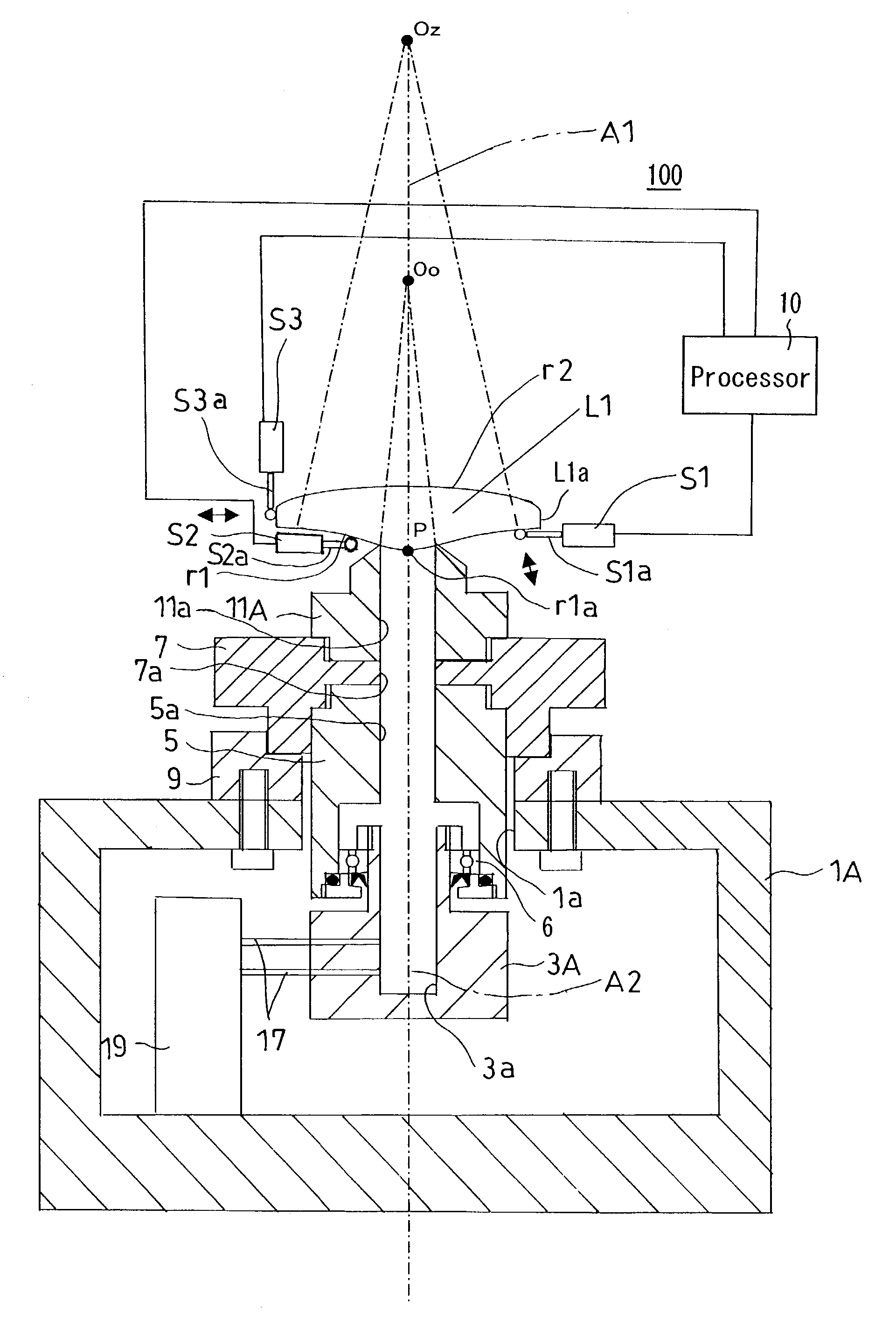
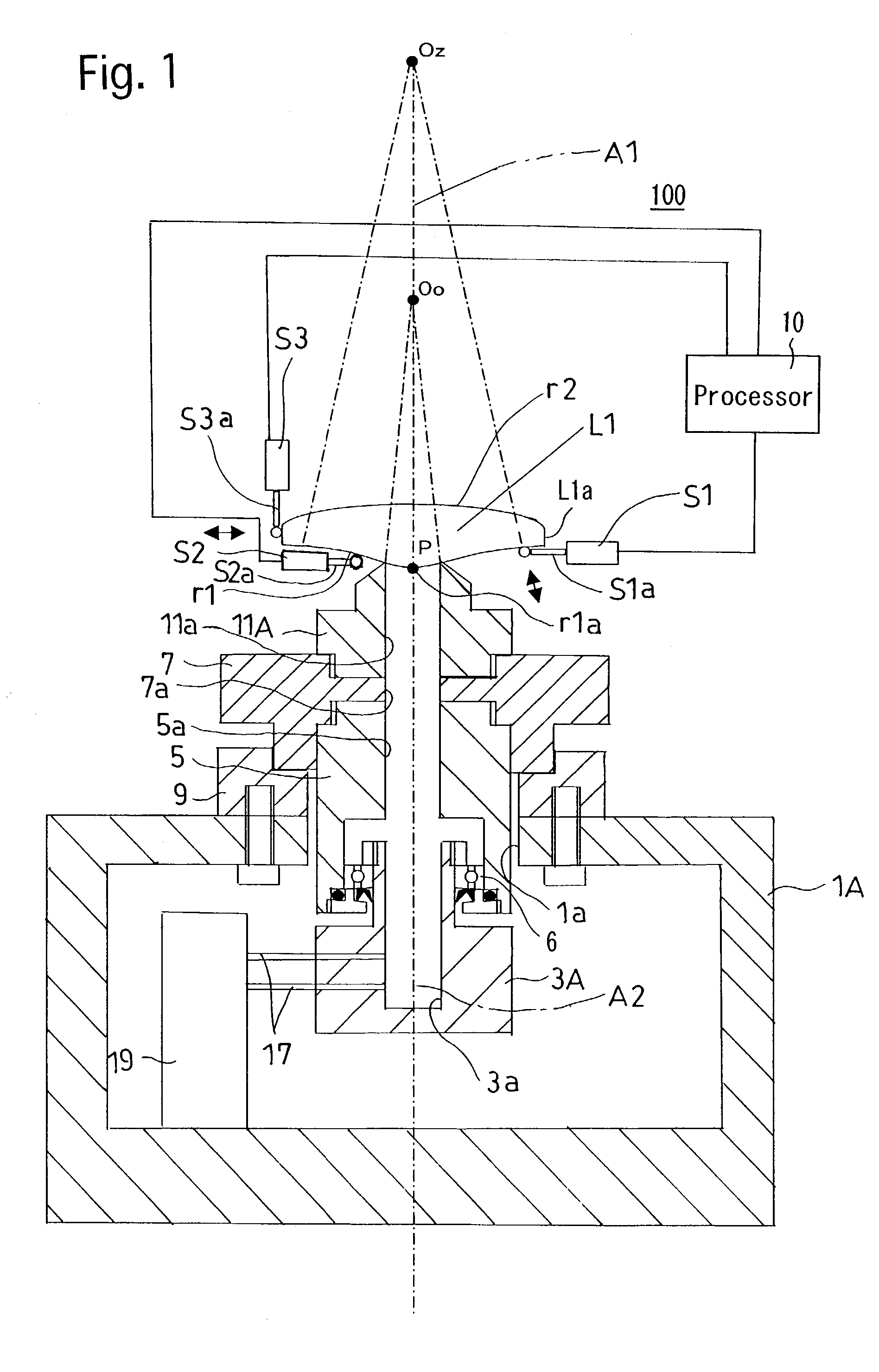
[0041]the apparatus for measuring an eccentricity of an optical lens according to the present invention will be hereinafter discussed with reference to FIG. 1.

[0042]The eccentricity measuring apparatus 100 shown in FIG. 1 is used to measure an eccentricity of an aspherical lens (optical lens) L1 which is provided on one and the other lens surfaces thereof with an aspherical surface r1 and a spherical surface r2, respectively. More specifically, the eccentricity measuring apparatus 100 is used to measure an eccentricity of the vertex of the aspherical surface r1 with respect to the radial center of the aspherical lens L1. This eccentricity is hereinafter referred to as an “eccentricity of the aspherical surface r1”, and is defined herein as a distance of a vertex r1a of the aspherical surface r1 (the point of intersection of the aspherical surface r1 with an aspherical-surface axis A1 thereof that linearly extends to trace a curvature center Oo of a central portion of the aspherical ...

second embodiment

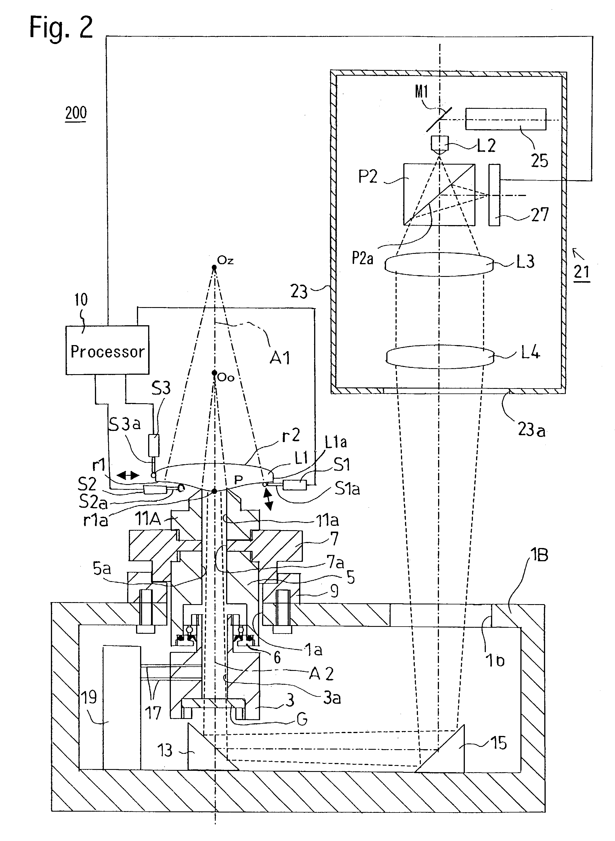
[0065]As can be seen from the above descriptions, according to the eccentricity measuring apparatus shown in FIG. 2, whether or not the curvature centers Oo is positioned on the axis A2 can visually be checked easily when the eccentricity of the aspherical surface r1 of the aspherical lens L1, which is provided on one and the other lens surfaces thereof with the aspherical surface r1 and the spherical surface r2, respectively, is measured. This makes it possible to measure the eccentricity of the aspherical surface r1 with a higher degree of precision.

[0066]The third embodiment of the apparatus for measuring an eccentricity of an optical lens according to the present invention will be hereinafter discussed with reference to FIG. 3. In the third embodiment of the eccentricity measuring apparatus, elements and parts similar to those in the second embodiment of the eccentricity measuring apparatus are designated by the same reference numerals, and will not be hereinafter discussed for ...

third embodiment

[0067]In the third embodiment, an eccentricity measuring apparatus 300 is used to measure the eccentricity of the aspherical surface r1 of the aspherical lens L1, which is provided on one and the other lens surfaces thereof with the aspherical surface r1 and the spherical surface r2, respectively, and an eccentricity of the curvature center Os of the spherical surface r2 with respect to the aspherical-surface axis A1 of the aspherical surface r1. This eccentricity is hereinafter referred to as an “eccentricity of the spherical surface r2”, and is defined herein as a distance of the curvature center Os from the aspherical-surface axis A1 in a radial direction of the aspherical lens L1.

[0068]Only elements and parts unique to the third embodiment of the eccentricity measuring apparatus 300, which are not incorporated in the second embodiment of the eccentricity measuring apparatus 200, will be hereinafter discussed.

[0069]The eccentricity measuring apparatus 300 is provided above the as...


PUM


Abstract

An apparatus for measuring eccentricity of an optical lens includes a rotary lens holder which supports a first lens surface of an optical lens by vacuum aspiration; a first determining device for determining whether a curvature center of a central portion of the first lens surface is positioned on the rotational axis; a second determining device for determining whether a curvature center of a peripheral portion of the first lens surface is positioned on the rotational axis; and an eccentricity detection device which detects an eccentricity of the optical lens with respect to the rotational axis to calculate an eccentricity of a vertex of the first lens surface with respect to the radial center of the optical lens, including a detector contacts a rim of the optical lens to detect the eccentricity of the optical lens with respect to the rotational axis.

Description

BACKGROUND OF THE INVENTION[0001]1. Field of the Invention[0002]The present invention relates to a method and an apparatus for measuring an eccentricity of the vertex of an aspherical surface of an aspherical lens (at least one lens surface of which is formed as an aspherical surface) with respect to the radial center of the aspherical lens, an eccentricity of the curvature center of the other lens surface thereof (an aspherical lens surface or a spherical lens surface), and the degree of deviation of the other lens surface. The present invention also relates to a method and an apparatus for centering and edging an optical lens (at least one lens surface of which is formed as an aspherical surface) while reducing an eccentricity of the vertex of an aspherical surface of the optical lens with respect to the true aspherical-surface axis of the aspherical lens surface of the optical lens even if the optical lens is a tilted aspherical lens.[0003]2. Description of the Related Art[0004]I...

Claims


Application Information

Patent Timeline
IPC IPC(8): G01B9/00G01M11/02
CPCG01M11/0221B29D11/00942
Inventor ITO, TAKAYUKI
Owner ASAHI KOGAKU KOGYO KK
Learn More