Motor for an electric power steering apparatus

a technology of electric power steering and motor, which is applied in the direction of mechanical energy handling, association with control/drive circuit, transportation and packaging, etc., can solve the problems of likely generation of vibrations and noises, and achieve the effect of preventing vibrations and noises from being amplified and reducing the eccentricity of the center of gravity of the motor from the output sha

Active Publication Date: 2011-11-17
MITSUBISHI ELECTRIC CORP
View PDF21 Cites 15 Cited by
  • Summary
  • Abstract
  • Description
  • Claims
  • Application Information

AI Technical Summary

Benefits of technology

[0006]According to the motor for an electric power steering apparatus according to the present invention, the controller is provided between the coupling and the motor section so as to surround the output shaft. Therefore, the amount of eccentricity of a center of gravity of the motor from the output shaft can be reduced. Hence, even if an electromagnetic force for deforming the stator core into an ellipsoidal shape is exerted on the stator core, vibrations and noises can be prevented from being amplified.

Problems solved by technology

Accordingly, there is a problem in that vibrations and noises are likely to be generated.

Method used


Image

  • Motor for an electric power steering apparatus
  • Motor for an electric power steering apparatus
  • Motor for an electric power steering apparatus

Examples


first embodiment

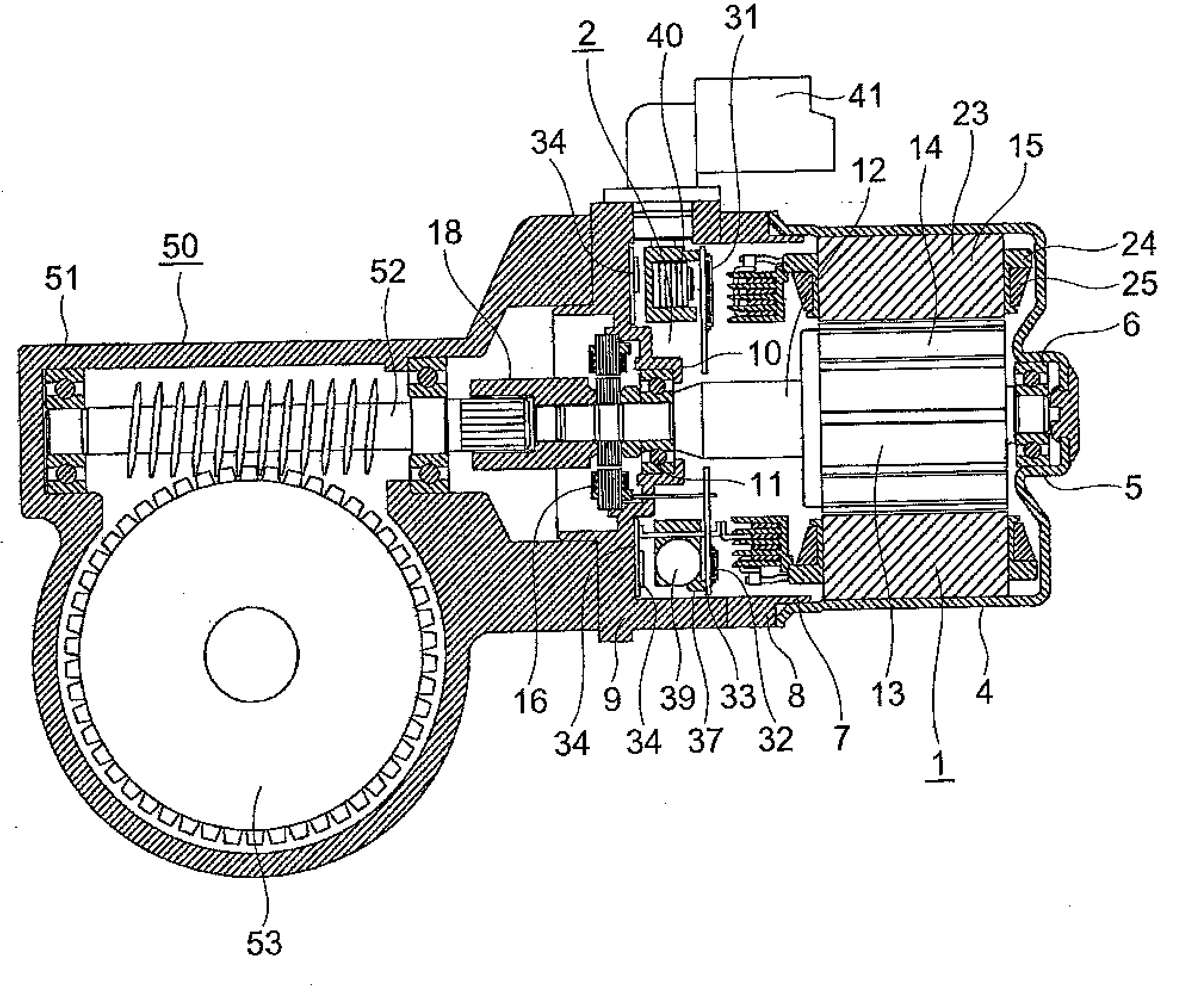
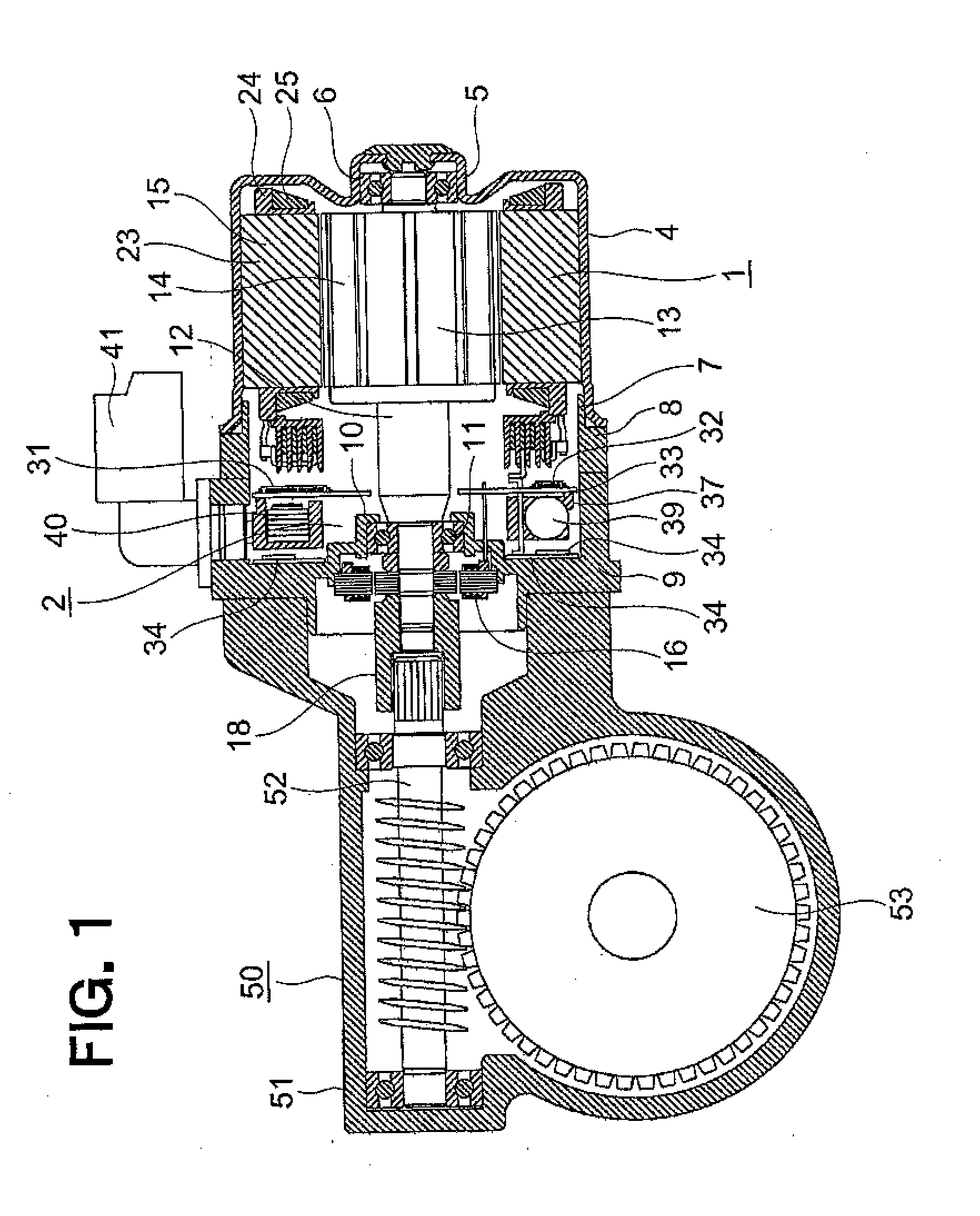
[0017]FIG. 1 is a side sectional view illustrating a motor for an electric power steering apparatus (hereinafter, abbreviated as “motor”) according to a first embodiment of the present invention, which includes a speed reducer mechanism 50. FIG. 2 is a side sectional view illustrating the motor illustrated in FIG. 1. FIG. 3 is an electric circuit diagram illustrating the motor illustrated in FIG. 1. FIG. 4 is a front sectional view illustrating a motor section 1 illustrated in FIG. 1.

[0018]The motor includes: the motor section 1 for outputting an assist torque to a handle of a vehicle (not shown); and a controller 2 for controlling the supply of a current from a battery 3 to the motor section 1 so as to control the driving of the motor section 1.

[0019]The motor section 1, which is a three-phase brushless motor, includes: a cylindrical frame 4 having a closed end; a rear bearing 6; a motor section-side case 8 having a cylindrical shape; and a speed reducer mechanism-side case 9 havin...

second embodiment

[0055]FIG. 5 is a front sectional view illustrating the motor section 1 according to a second embodiment of the present invention.

[0056]In this second embodiment, the number P of poles and the number n of slots satisfy relations: P:n=14:12, and therefore, p−n=2. The winding portions are arranged in the order of: U1+, U1−, W1−, W1+, V1+, V1−, U2−, U2+, W2+, W2−, V2−, and V2+ in the counterclockwise direction of FIG. 5 (the signs + and − means that the directions of windings are opposite to each other).

[0057]At the position which is opposed to one winding portion so as to be 180 degrees in mechanical angle (corresponding to six slots) apart, the winding portion of the same phase is provided. At the position 120 degrees (corresponding to four slots) or 90 degrees (corresponding to three slots) apart, the winding portion of the same phase is not provided.

[0058]Specifically, the motor according to the second embodiment is the same as that of the first embodiment except that the number of...

third embodiment

[0062]FIG. 6 is a side sectional view illustrating a stator 15A of the motor according to a third embodiment of the present invention, whereas FIG. 7 is a front sectional view illustrating the motor illustrated in FIG. 6.

[0063]In this third embodiment, clearances A in the slots 22 and those between the frame 4 and the stator core 23 are filled with a resin 60. The resin 60 is a resin having a relatively high hardness such as unsaturated polyester and epoxy and has the effects of increasing the rigidity of the stator 15A.

[0064]The remaining structure is the same as that of the motor according to the first embodiment.

[0065]The clearances A lock the stator core 23 for the positioning thereof at the time when the stator windings 25 are wound around the stator core 23. The clearances A also serve to reduce a force for pressing the stator core 23 into the frame 4.

[0066]According to the motor described above, even if the electromagnetic force for deforming the stator core 23 into the ellip...


PUM


Abstract

Provided is a motor for an electric power steering apparatus, in which vibrations and noises are suppressed. The motor for an electric power steering apparatus includes: a motor section (1) for outputting an assist torque to a handle of a vehicle; and a controller (2) for controlling driving of the motor section (1). The motor section (1) includes: a rotor (14, 14A) having P poles; and a stator (15, 15A) provided so as to surround the rotor (14, 14A), the stator including: a stator core (23) provided with n slots formed thereon and housed in a frame (4); and three-phase stator windings (25) wound around the slots (22). The controller (2) is provided between a boss (18) and the motor section (1) so as to surround the output shaft (12).

Description

BACKGROUND OF THE INVENTION[0001]The present invention relates to a motor for an electric power steering apparatus, which is mounted to a vehicle to assist a steering force applied by a driver.[0002]As a conventional motor for controller integrated electric power steering apparatus, a motor including a controller provided on a side surface portion of a motor section is known (for example, see JP 3593102 B (pages 5 to 8, and FIGS. 1 and 2).[0003]In the motor for electric power steering apparatus, described in JP 3593102 B, however, the controller, which is a heavy load, is mounted onto the side surface portion of the motor section. Therefore, a center of gravity of the motor is located radially eccentrically from an output shaft. Accordingly, there is a problem in that vibrations and noises are likely to be generated.SUMMARY OF THE INVENTION[0004]The present invention has been made to solve the problem described above, and therefore has an object to provide a motor for an electric po...

Claims


Application Information

Patent Timeline
Patent Type & Authority Applications(United States)
IPC IPC(8): H02K11/00
CPCB62D5/0403B62D5/0406H02K7/1166H02K2213/03H02K11/0073H02K21/16H02K11/0031H02K11/225H02K11/33
Inventor AKUTSU, SATORUTAKASHIMA, KAZUHISAASAO, YOSHIHITO
Owner MITSUBISHI ELECTRIC CORP
Why Eureka
Try Eureka