
Hydrodynamic clutch device

a clutch device and hydraulic technology, applied in the direction of rotary clutches, fluid couplings, gearings, etc., to achieve the effects of preventing an unbraked acceleration of the drive, increasing pressure, and great sensitivity

Inactive Publication Date: 2006-09-21
ZF FRIEDRICHSHAFEN AG
View PDF4 Cites 10 Cited by
  • Summary
  • Abstract
  • Description
  • Claims
  • Application Information

AI Technical Summary

Benefits of technology

The invention is a hydrodynamic clutch device with a bridging clutch that can be closed without causing any surge in torque during operation in push mode. This is achieved by installing a pressure barrier between the hydrodynamic circuit and the pressure space, which prevents any exchange of clutch fluid between the two spaces. The pressure barrier is designed to compensate for any movement of the piston during operation. The device allows for a smooth and controlled engagement of the piston, resulting in improved driving comfort for the vehicle.

Problems solved by technology

Because of the pressure barrier between the hydrodynamic circuit and the pressure space, however, these two pressure-increase curves will not undergo any equalization even in the area of the radial extension of the bridging clutch and even when the piston is released.

Method used


Image

  • Hydrodynamic clutch device
  • Hydrodynamic clutch device

Examples


Embodiment Construction

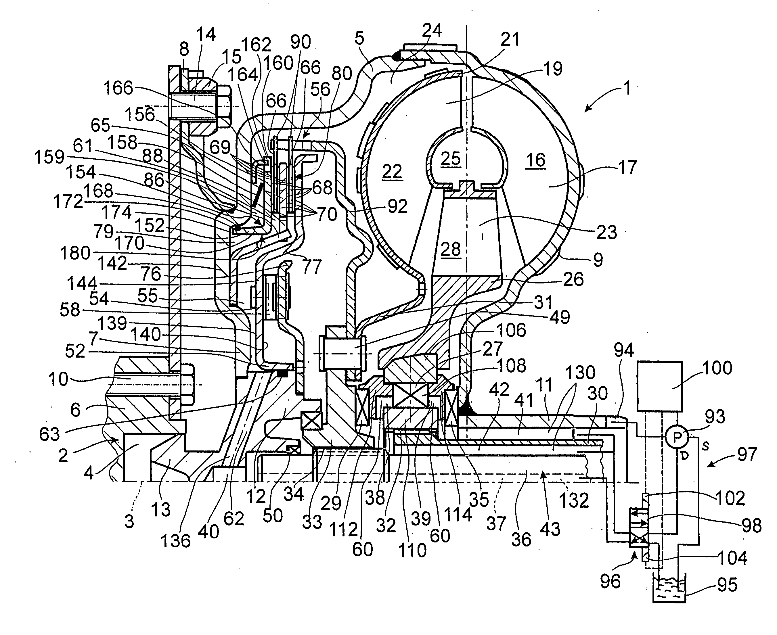
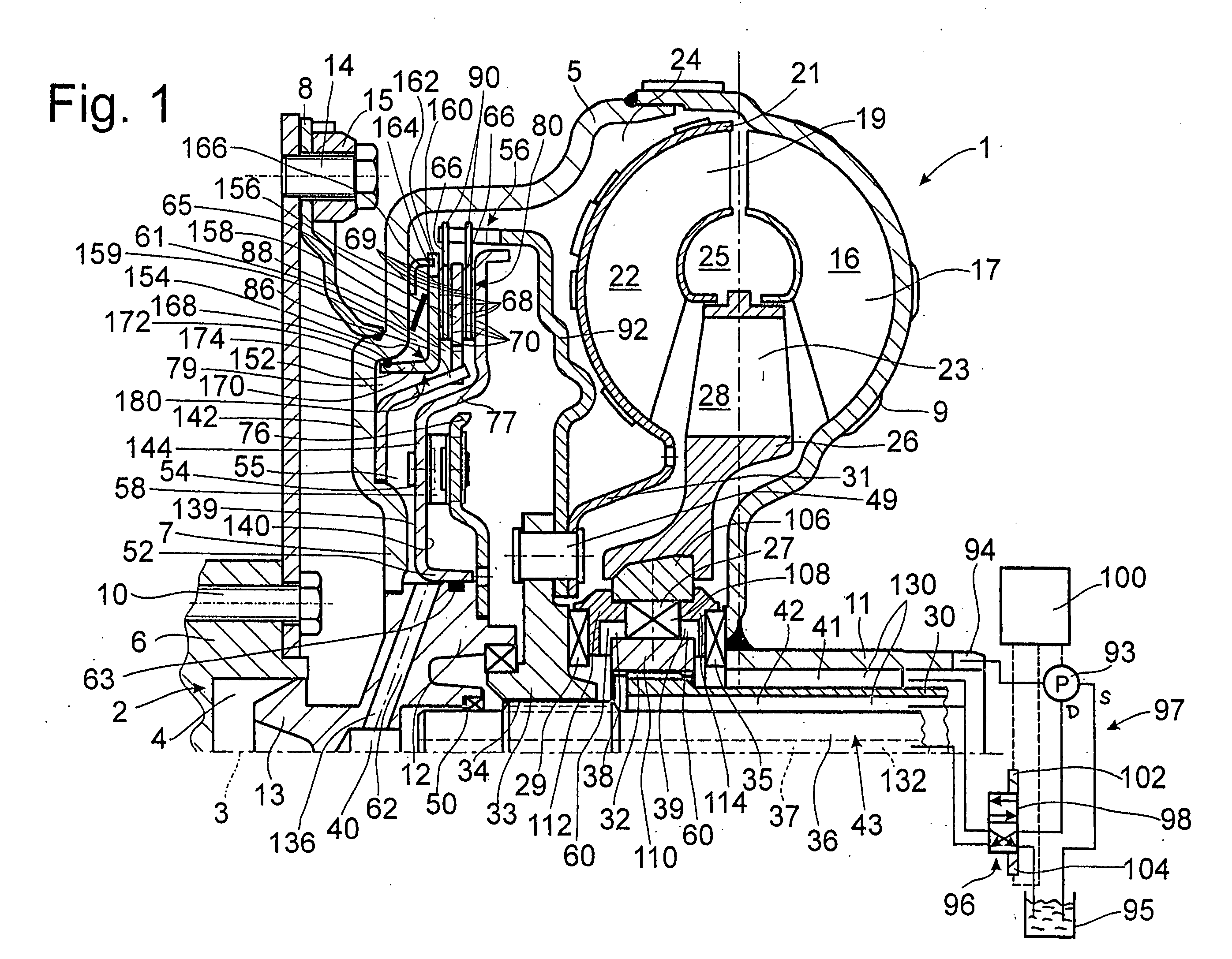
[0023] The FIGURE shows a hydrodynamic clutch device 1 in the form of a hydrodynamic torque converter, which is able to execute rotational movement around an axis of rotation 3. The hydrodynamic torque converter has a clutch housing 5 with a housing cover 7 on the side facing a drive 2, such as an internal combustion engine with a crankshaft 6. The housing cover is permanently connected to a pump wheel shell 9. This shell merges in its radially inner area with a pump wheel hub 11.

[0024] In its radially inner area, the housing cover 7 has a journal hub 12, which carries a bearing journal 13. The bearing journal 13 is held in a recess 4 in the crankshaft 6 for the purpose of centering the clutch housing 5 on the drive side. The housing cover 7 also has a fastening mount 15, by which the clutch housing 5 is fastened to the crankshaft by way of a flexplate 8, this being accomplished by the use of fastening elements 14, preferably in the form of screws. The flexplate 8 for its own part ...


PUM


Abstract

A hydrodynamic clutch device has at least one pump wheel, connected to a drive by way of a clutch housing, and a turbine wheel, connected to a takeoff, to form a hydrodynamic circuit. The device also has a bridging clutch with at least one piston, which can shift between a released position and an engaged position, and at least one friction surface acting between this piston and an adjacent support to connect the drive to the takeoff. When the piston is in the released position, the bridging clutch allows the hydrodynamic circuit to be used to transmit at least most of the torque between the drive and takeoff, whereas, when the piston is in the engaged position, the bridging clutch produces a bypass around the hydrodynamic circuit for the transmission of torque. The barrier clutch cooperates with at least one pressure barrier installed between the hydrodynamic circuit and the pressure space. This separation more-or-less completely prevents the exchange of clutch fluid between the hydrodynamic circuit and the pressure space, regardless of the instantaneous position of the piston between its released position and its engaged position and thus regardless of the shift status of the bridging clutch.

Description

BACKGROUND OF THE INVENTION [0001] 1. Field of the Invention [0002] The invention pertains to a hydrodynamic clutch device including a pump wheel; a housing connecting the pump wheel to a drive; a turbine wheel connected to a takeoff, and cooperating with the pump wheel to form a hydrodynamic circuit; a bridging clutch having a piston movable between an engaged position, wherein the drive transmits torque to the takeoff via the bridging clutch, and a released position, wherein the drive transmits torque to the takeoff via the hydrodynamic circuit; and a pressure circuit including a first pressure medium line which supplies clutch fluid to the hydrodynamic circuit, and a second pressure medium line which supplies clutch fluid to the pressure space. [0003] 2. Description of the Related Art [0004] U.S. Pat. No. 5,575,363 describes a hydrodynamic clutch device designed as a hydrodynamic torque converter. This device comprises a clutch housing, which is brought into connection in the con...

Claims


Application Information

Patent Timeline
Patent Type & Authority Applications(United States)
IPC IPC(8): F16H45/02
CPCF16H45/02F16H2045/0284
Inventor ACKERMANN, JURGENADELMANN, THOMASGAJDA, CHRISTOPH
Owner ZF FRIEDRICHSHAFEN AG
Learn More