
Stand, in particular for surgical microscopes, having an energy storage element

a technology of energy storage element and stand, which is applied in the field of stand, can solve the problems of insufficient working range of conventional gas springs and present bracing effect, and achieve the effect of reducing the disadvantageous cosine effect of horizontal support and removing the disadvantageous effect of horizontal suppor

Inactive Publication Date: 2005-10-13
LEICA MICROSYSTEMS (SCHWEIZ) AG
View PDF30 Cites 18 Cited by
  • Summary
  • Abstract
  • Description
  • Claims
  • Application Information

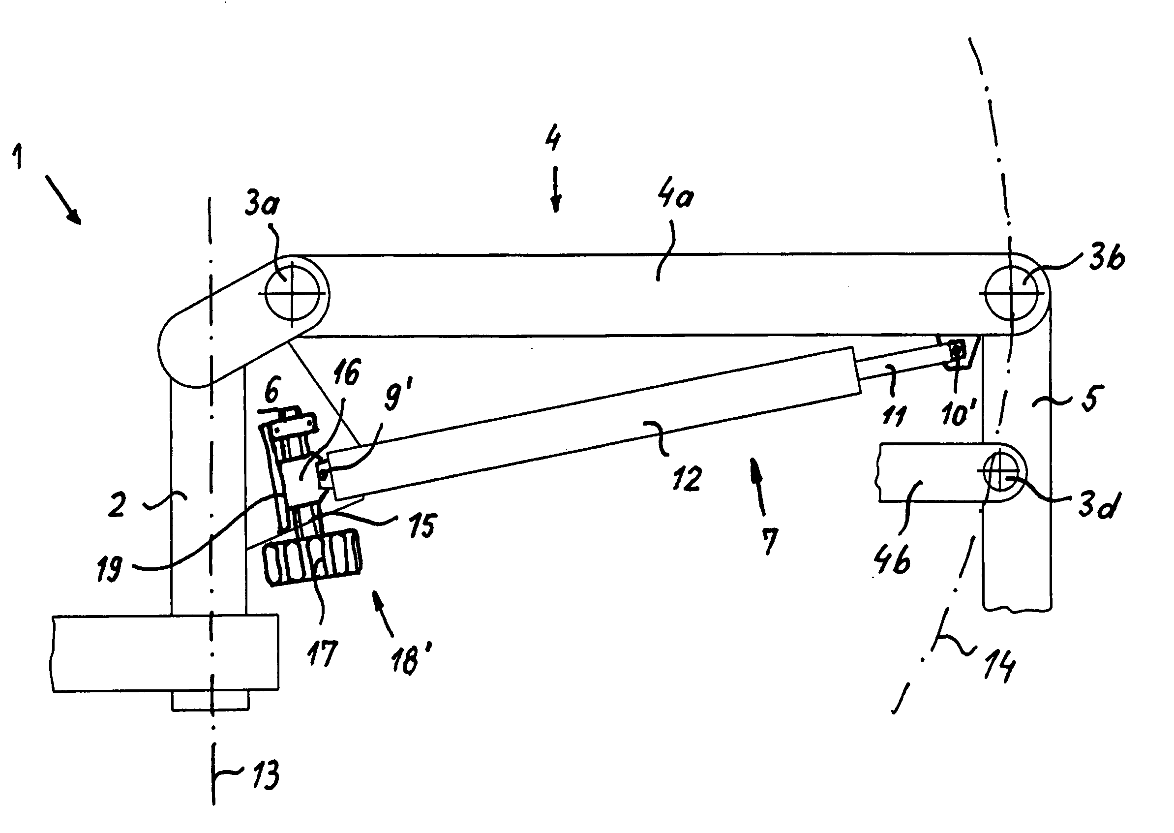
AI Technical Summary

Benefits of technology

[0009] It is thus the object of the invention to arrive at an improved system having energy-storage-element bracing, in particular gas-spring bracing, that is adjustable to different loads on the one hand so as thereby to eliminate the interchanging of different gas springs for different loads, and on the other hand in order to eliminate the disadvantageous cosine effect of the horizontal support under the load of the microscope, or reduce it sufficiently that it is no longer an annoyance. The toggle-lever jump effect is also to be eliminated. At the same time, the energy storage element must meet the typical requirements for a surgical microscope stand, i.e. the energy storage element must be capable of absorbing a counterbalancing force of approximately 2000 N. Conventionally, however, such high-rated energy storage elements exhibit a spring progression of approximately 18%.
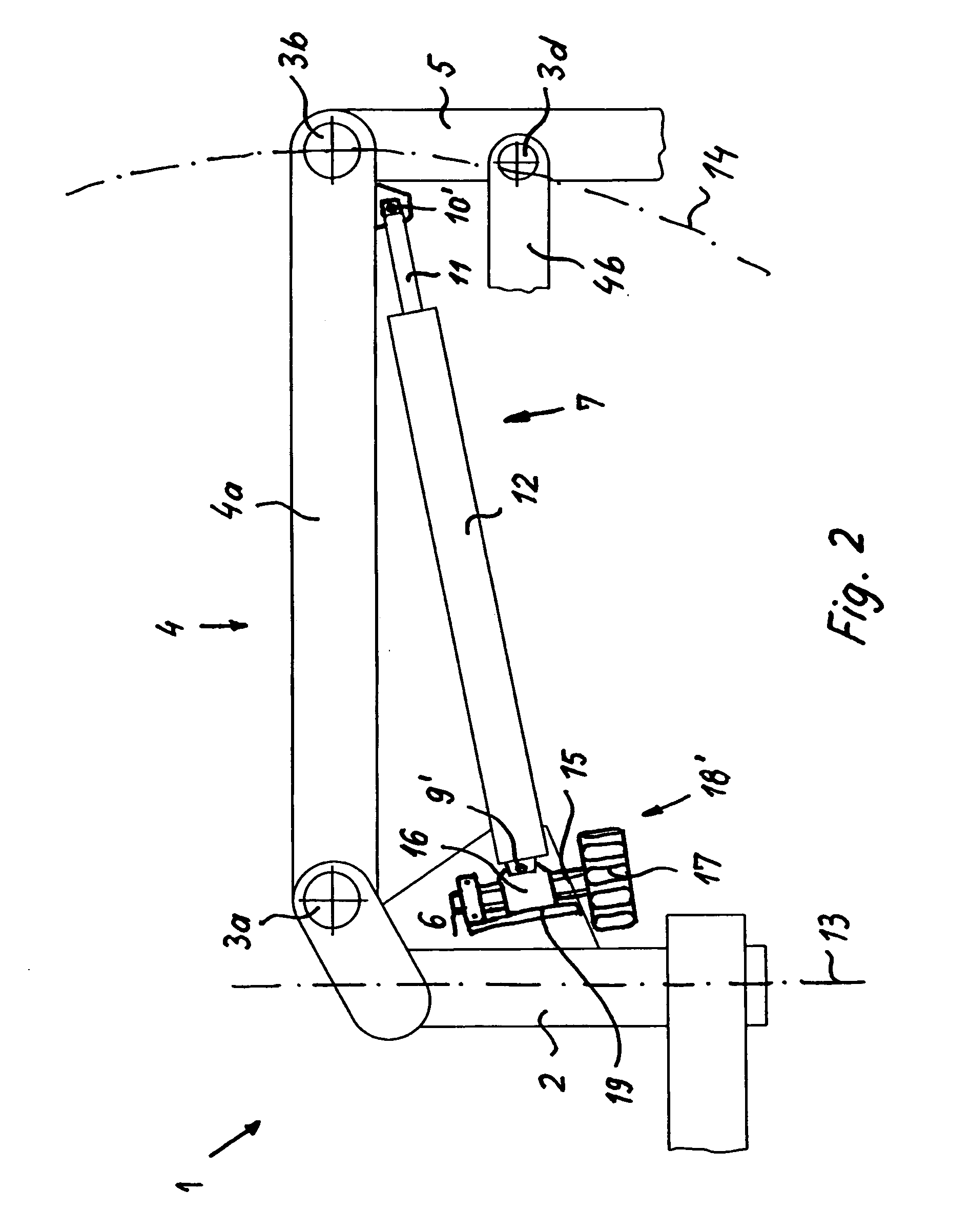
[0011] Simultaneously or alternatively, these objects can be achieved by the fact that in novel fashion, instead of the conventional installation of the gas spring piston rod on the vertical support and of the gas spring cylinder on the horizontal support, it is the gas spring cylinder and not the gas spring piston rod that is articulated at the displaceable mounting point of the vertical support. The gas spring piston rod is thus, in novel fashion, preferably articulated as far out as possible at the distal end of the horizontal support. On the one hand this reduces the disadvantageous effect of the cosine function of the load, since the weight of the cylinder is shifted from the distal end of the horizontal support closer to the vertical support. An additional result is that a smaller annoying variable magnitude is present, which in novel fashion is no longer determined by a larger shiftable cylinder mass but instead by a smaller shiftable piston-rod mass. On the other hand, a gas spring of the greatest possible length exhibits better hysteresis properties (because of larger pressure chambers and, associated therewith, a lower potential pressure in the gas spring).
[0012] It is also preferred, for the sake of larger pressure chambers (so that the spring progression value is lower) and better hysteresis properties associated therewith, to select gas springs having the largest possible cylinder diameters.
[0013] A further preferred embodiment of a gas spring designed specifically for the desired applications has the smallest possible outside diameter for the piston rod. This design feature once again makes it possible to improve the hysteresis properties and, most of all, to lower the static friction, in particular the necessary “breakaway” force, at the cost of an increase in dynamic friction.
[0014] A further action that, according to the present invention, improves the gas spring is to bore out the nozzles in the piston. In conventional gas springs the diameter of these nozzles is in the range of tenths of a millimeter; in novel fashion, however, it is increased to no less than 2 mm, preferably 4 mm. Static friction is thereby minimized.

Problems solved by technology

This is necessary because the working range of conventional gas springs has insufficient bandwidth.
Conventional gas-spring-braced stands have the disadvantage that because of the so-called “cosine function” of the load lever effect of the microscope along its vertical movement arc, the bracing effect that is present differs as a function of the angular position of the horizontal support with respect to the vertical support.
It has been found in practical use, however, that this configuration is disadvantageous in that the proximal end of the piston rod does not move continuously in the arc-shaped elongated guidance hole but instead, when used, jumps from one extreme position to the other in the manner of a toggle lever; for a user, this requires an additional movement across the jumping point in order to achieve readjustment of the support conditions in the arc-shaped elongated guidance hole.

Method used


Image

  • Stand, in particular for surgical microscopes, having an energy storage element
  • Stand, in particular for surgical microscopes, having an energy storage element
  • Stand, in particular for surgical microscopes, having an energy storage element

Examples


Embodiment Construction

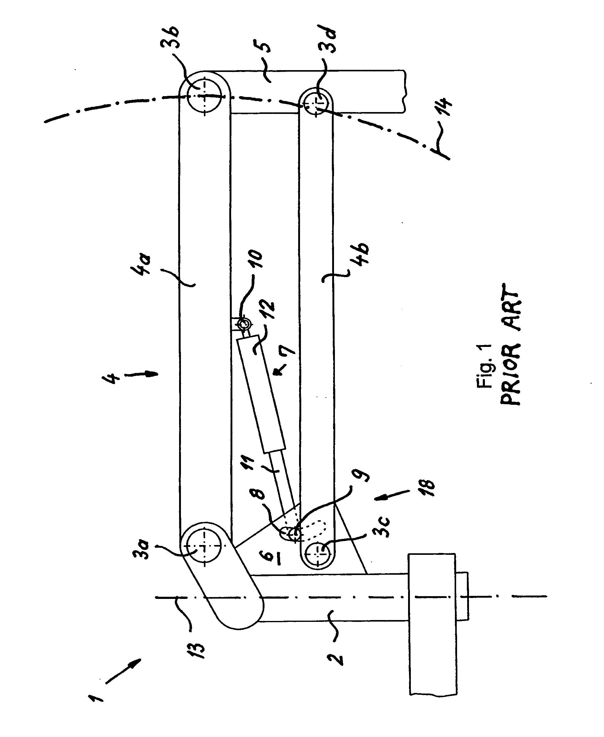
[0025]FIG. 1 schematically depicts a stand arrangement 1 according to the existing art. Stand 1 comprises a vertical support 2 and a horizontal support 4 that is implemented as a parallelogram support having an upper horizontal support arm 4a and a lower horizontal support arm 4b. A gas spring is arranged, as a supporting energy storage element 7, at an articulation point 10 on upper horizontal support arm 4a of horizontal support 4 and at an articulation point 9 in a plate 6. Stand 1 has, as a means for positively influencing hysteresis properties, a displacement apparatus 18 that does not act linearly but instead permits, by way of an arc-shaped elongated guide hole 8, a radial displacement of articulation point 9.

[0026] Gas spring 7 is arranged with a cylinder 12 at distal articulation point 10 and with a piston rod 11 at articulation point 9.

[0027] This stand arrangement furthermore comprises joints 3a-d and a microscope carrier 5. Horizontal support 4 pivots about pivot axis ...


PUM


Abstract

The invention concerns a stand arrangement (1) having a particularly arranged energy storage element (7) with specific parameters, in particular a low spring progression. The static friction is thereby reduced to a minimum.

Description

CROSS REFERENCE TO RELATED APPLICATIONS [0001] This application claims priority of the German patent application 10 2004 017 971.9 filed Apr. 12, 2004, which application is incorporated by reference herein. FIELD OF THE INVENTION [0002] The invention concerns a stand, in particular a stand for a surgical microscope, having one or more energy storage elements. “Energy storage elements” are understood in general to be elements that are suitable for absorbing an energy or force and delivering it again, or converting it into a different form of energy, in defined fashion. Relevant in this context are springs of mechanical, pneumatic, or hydraulic type or a combination of such types, or shock absorbers. Gas springs are primarily used in stand construction, in particular for surgical microscopes, but springs of the other aforementioned types are also implemented. BACKGROUND OF THE INVENTION [0003] In order to achieve a maximally space-saving stand configuration, stands having energy stora...

Claims


Application Information

Patent Timeline
IPC IPC(8): F16F9/02F16M11/04A61B19/00G02B21/24G02B7/00
CPCF16F9/0209F16M11/18F16M11/2064F16M2200/044G02B7/001A61B90/50A61B90/20A61B2090/5025A61B2090/506
Inventor METELSKI, ANDRZEJ
Owner LEICA MICROSYSTEMS (SCHWEIZ) AG
Learn More