Cooling medium flow passage

a flow passage and cooling medium technology, applied in the field of cooling liquid, can solve the problems of increasing the failure rate of the inverter, the inability to get sufficient mobile performance, and the decrease of the generated torque of the motor, so as to reduce the trouble, improve the cooling efficiency of the motor, and improve the performance of the motor.

Inactive Publication Date: 2009-01-27
KANKYOKIKI CORP
View PDF37 Cites 16 Cited by
  • Summary
  • Abstract
  • Description
  • Claims
  • Application Information

AI Technical Summary

Benefits of technology

[0021]According to the present invention, cooling efficiency of a motor may be improved in a very simply manner and, as a result, performance of the motor may be improved. According to the present invention, a reduction of troubles such as failures of an inverter including a motor, prevention of clogging and contamination of pipes of a liquid-cooling system, a reduction of pump failures, a saving in consumption energy and a reduction of the number of replacements of water or antifreeze liquid and so on can be attained.
[0022]According to the present invention, attaching a liquid activator or magnets to the liquid-cooling system of the motor enables to break apart clusters of molecules of a liquid such as water or an antifreeze liquid and so on, and easily replacing a cooling system instead of the motor as a whole enables to improve efficiency, performance, safety and failure tolerance of motor- and inverter-cooling lines. In addition, the load on a pump in the system is greatly reduced to provide a similar result.
[0023]According to the present invention, efficient suppression of heat generation of the motor will cause such effects as increasing motor outputs, extending the useful life of the motor, lessening heat losses, decreasing failures, eliminating ununiformness of output and torque and reducing electric power consumption.
[0024]Also, according to the present invention, efficient suppression of heat generation of the inverter will cause such effects as extending the useful life of the inverter, increasing motor output, decreasing failures, eliminating ununiformness of output and torque, facilitating controls and reducing electric power consumption.
[0025]According to the present invention, flowing of a liquid having small clusters of molecules to greatly reduce the load on the pump will cause such effects as increasing the flow velocity of the cooling liquid to increase the cooling capability, reducing pump failures and preventing stain buildup inside the pipes to extend the useful life and sustain the flow velocity.
[0026]According to the present invention, the frequency of cooling liquid replacement is greatly reduced and the apparatus can be used semipermanently because it is composed of only permanent magnets or of permanent magnets combined with far-infrared ray-generating stones. It can therefore be used repeatedly if it would be formed as a detachable unit.

Problems solved by technology

When the heat generation grows to increase the motor temperature, problems will arise, such as a decrease of generated torque of the motor and an increase of inverter failure rate.
On the other hand, the electric vehicle has a disadvantage that it cannot get sufficient mobile performance in comparison to the gasoline vehicle.
Such modifications of designs are necessary, but a huge amount of cost and time for development will be necessary.
When a currently available motor is used for an electric vehicle, problems are that its output is small in relation to battery capacity and motor output is small.
Otherwise, the temperature of a motor or an inverter for drive control would excessively increase, preventing a wanted output from being obtained at high-revolution, high-output ranges.
These solutions will, however, be contradictory to the objectives as described above, such as reduction in size and weight, improvement in performance and durability and reduction in cost for a motor.

Method used


Image

  • Cooling medium flow passage
  • Cooling medium flow passage
  • Cooling medium flow passage

Examples


examples

[0034]Embodiments of magnetic members, such as magnets, for generating a magnetic force to be used in the present invention will be described.

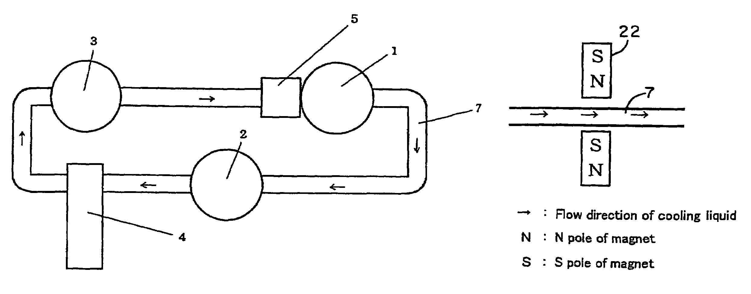
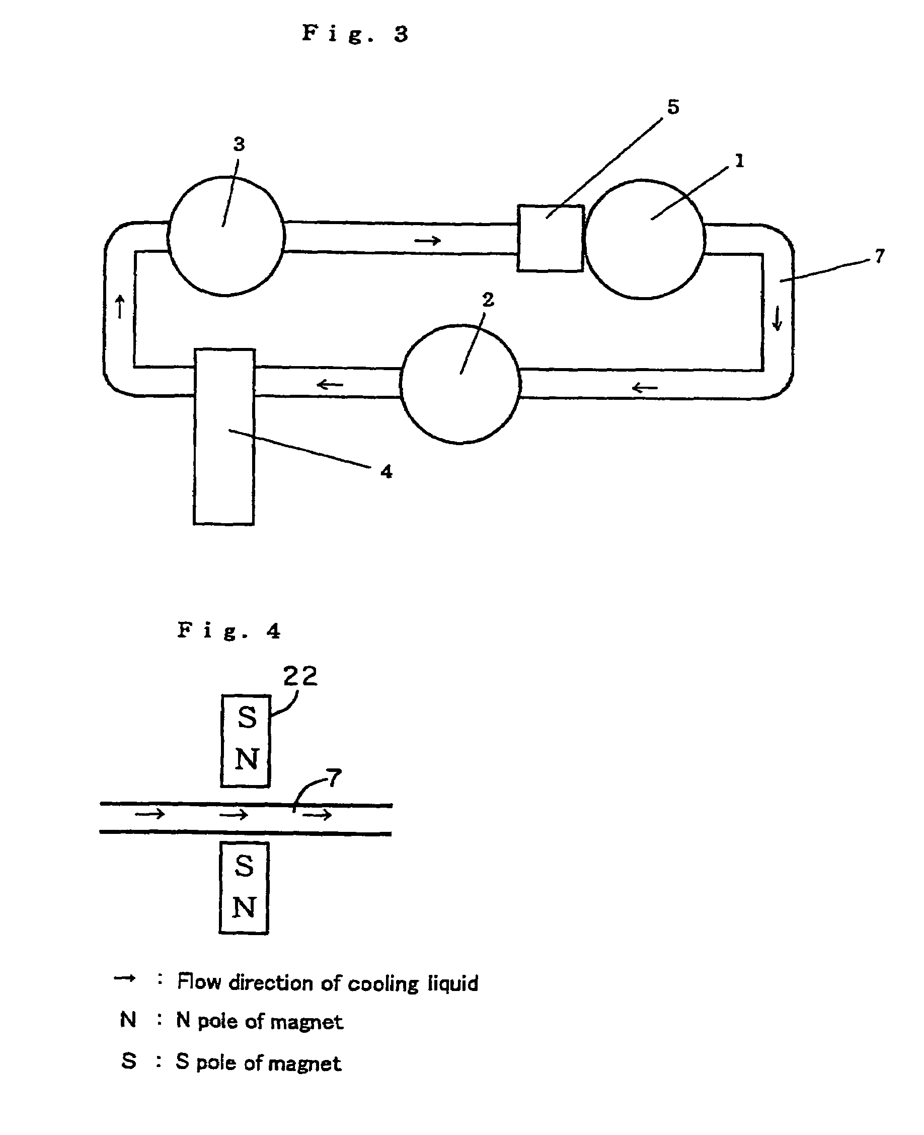
[0035]A first embodiment is shown in FIG. 4. This figure represents a manner in which unipolar magnets 22 are mounted at any location where water or antifreeze liquid and so on flows in a liquid-cooling system for a motor. With reference to FIG. 4, arrows represent the flow direction of cooling liquid and “N” denotes the N pole of a magnet while “S” denotes the S pole of the magnet (here and hereinafter).

[0036]A second embodiment of magnetic members according to the present invention is shown in FIG. 5. This figure represents a manner in which multiple multipolar magnets are mounted along a cooling liquid path. As shown in FIG. 5, adjacent magnet units 27 are desirably mounted with their N poles and S poles in an alternate fashion.

[0037]FIG. 6 shows a variant of the second embodiment. This embodiment also represents a manner in which multiple ...


PUM

PropertyMeasurementUnit
wavelengthaaaaaaaaaa

Abstract

The present invention provides a cooling medium flow path for improving cooling efficiency of a cooling medium used for liquid-cooling systems for motors, radiators and the like.The cooling medium flow path according to the present invention is capable of increasing cooling efficiency of a cooling medium by providing magnetic members for generating a magnetic force in a direction substantially perpendicular to the flow direction of the cooling medium so that clusters of a liquid, such as cooling water, antifreeze liquid or the like flowing through the flow path may be finely divided or activated.

Description

[0001]This application is a U.S. National Phase Application under 35 USC 371 of International Application PCT / JP2004 / 008894, filed Jun. 24, 2004, which is incorporated herein in its entirety by this reference.TECHNICAL FIELD[0002]The present invention relates to cooling liquid to be used for liquid-cooling systems for motors, radiators and the like, and more specifically, to a method of improving liquid-cooling efficiency of the cooling liquid.BACKGROUND ART[0003]A structure of a liquid-cooled motor is described with reference to FIG. 1 (a front view) and FIG. 2 (a side sectional view taken along A-A′ section of the front view). The motor rotates with its rotor 107 about its rotation axis 105. Alternating current flows in the rotor 107 and heat is generated due to an eddy current loss based on the alternating current. When the heat generation grows to increase the motor temperature, problems will arise, such as a decrease of generated torque of the motor and an increase of inverter ...

Claims


Application Information

Patent Timeline
Patent Type & Authority Patents(United States)
IPC IPC(8): C02F1/48B01J19/08H02K9/19B03C1/30B03C1/32C02F1/30B29C49/66C02F1/68C02F5/00F01P3/00F01P9/00F01P11/04F01P11/06H02K9/26
CPCC02F1/481F01P9/00F01P11/06H02K9/26B29C49/66F01P11/04F01P2003/001Y10T137/206
Inventor TAKAHASHI, KAZUMIKINOSHITA, MASAAKI
Owner KANKYOKIKI CORP
Why Eureka
Try Eureka