Cooling medium flow passage

Inactive Publication Date: 2007-01-25
KANKYOKIKI CORP
View PDF16 Cites 33 Cited by
  • Summary
  • Abstract
  • Description
  • Claims
  • Application Information

AI Technical Summary

Benefits of technology

[0020] According to the present invention, cooling efficiency of a motor may be improved in a very simply manner and, as a result, performance of the motor may be improved. According to the present invention, a reduction of troubles such as failures of an inverter including a motor, prevention of clogging and contamination of pipes of a liquid-cooling system, a reduction of pump failures, a saving in 5 consumption energy and a reduction of the number of replacements of water or antifreeze liquid and so on can be attained.
[0021] According to the present invention, attaching a liquid activator or magnets to the liquid-cooling system of the motor enables to break apart clusters of molecules of 10 a liquid such as water or an antifreeze liquid and so on, and easily replacing a cooling system instead of the motor as a whole enables to improve efficiency, performance, safety and failure tolerance of motor- and inverter-cooling lines. In addition, the load on a pump in the system is greatly reduced to provide a similar result.
[0022] According to the present invention, efficient suppression of heat generation of the motor will cause such effects as increasing motor outputs, extending the useful lif

Problems solved by technology

When the heat generation grows to increase the motor temperature, problems will arise, such as a decrease of generated torque of the motor and an increase of inverter failure rate.
On the other hand, the electric vehicle has a disadvantage that it cannot get sufficient mobile performance in comparison to the gasoline vehicle.
Such modifications of designs are necessary, but a huge amount of cost and time for development will be necessary.
When a currently available motor is used for an elect

Method used


Image

  • Cooling medium flow passage
  • Cooling medium flow passage
  • Cooling medium flow passage

Examples


examples

[0034] Embodiments of magnetic members, such as magnets, for generating a magnetic force to be used in the present invention will be described.

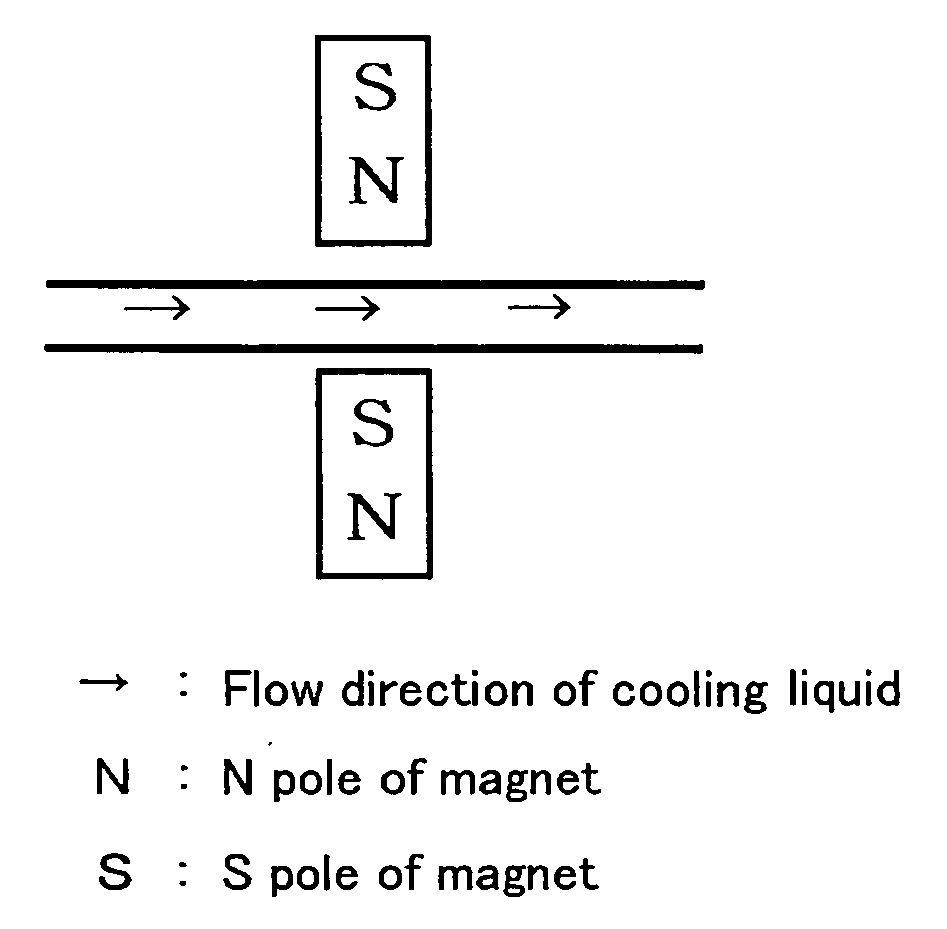
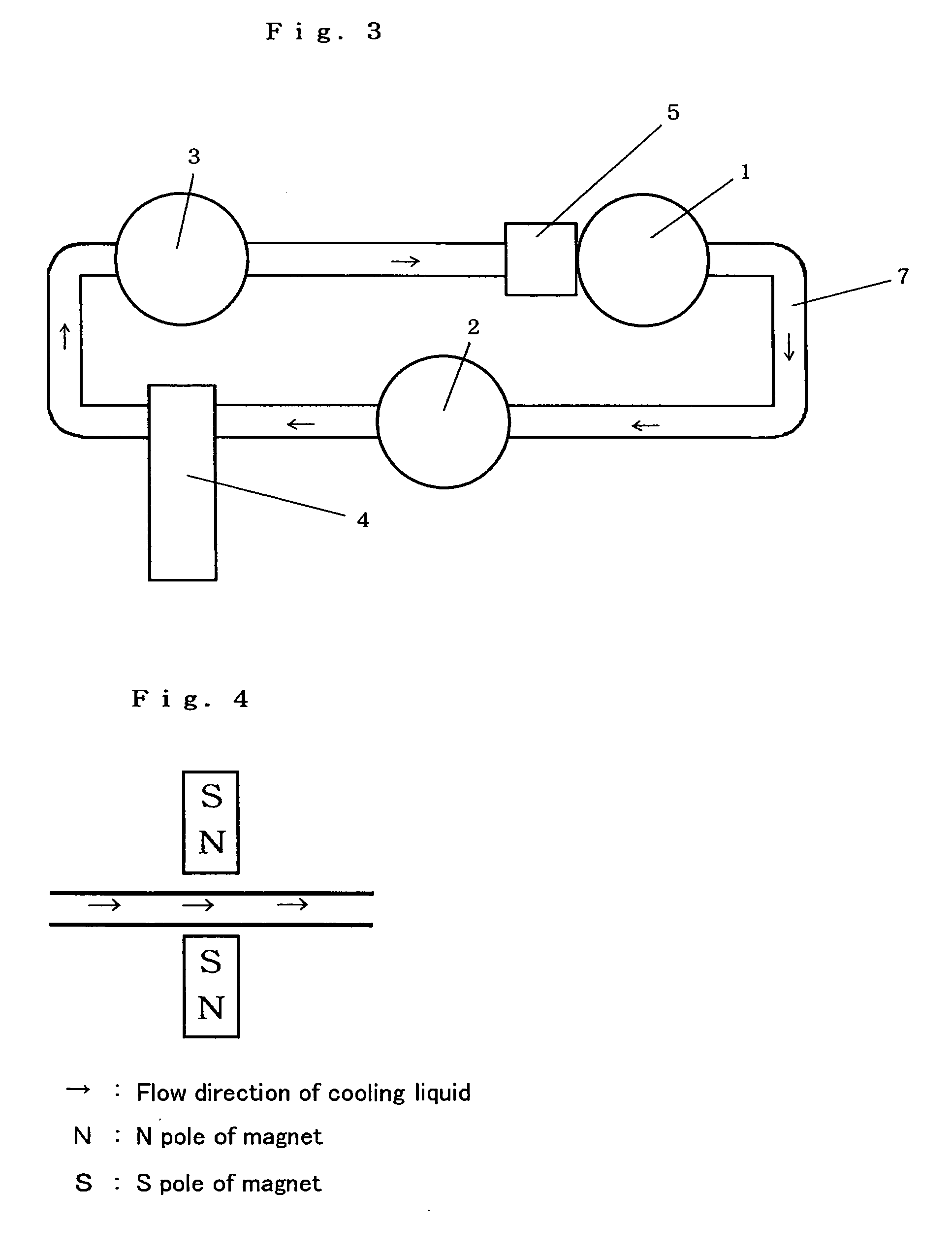
[0035] A first embodiment is shown in FIG. 4. This figure represents a manner in which unipolar magnets are mounted at any location where water or antifreeze liquid and so on flows in a liquid-cooling system for a motor. With reference to FIG. 4, arrows represent the flow direction of cooling liquid and “N” denotes the N pole of a magnet while “S” denotes the S pole of the magnet (here and hereinafter).

[0036] A second embodiment of magnetic members according to the present invention is shown in FIG. 5. This figure represents a manner in which multiple multipolar magnets are mounted along a cooling liquid path. As shown in FIG. 5, adjacent magnet units are desirably mounted with their N poles and S poles in an alternate fashion.

[0037]FIG. 6 shows a variant of the second embodiment. This embodiment also represents a manner in which multiple ...


PUM

PropertyMeasurementUnit
Fractionaaaaaaaaaa
Flow rateaaaaaaaaaa
Wavelengthaaaaaaaaaa

Abstract

The present invention provides a cooling medium flow path for improving cooling efficiency of a cooling medium used for liquid-cooling systems for motors, radiators and the like. The cooling medium flow path according to the present invention is capable of increasing cooling efficiency of a cooling medium by providing magnetic members for generating a magnetic force in a direction substantially perpendicular to the flow direction of the cooling medium so that clusters of a liquid, such as cooling water, antifreeze liquid or the like flowing through the flow path may be finely divided or activated.

Description

TECHNICAL FIELD [0001] The present invention relates to cooling liquid to be used for liquid-cooling systems for motors, radiators and the like, and more specifically, to a method of improving liquid-cooling efficiency of the cooling liquid. BACKGROUND ART [0002] A structure of a liquid-cooled motor is described with reference to FIG. 1 (a front view) and FIG. 2 (a side sectional view taken along A-A′ section of the front view). The motor rotates with its rotor 107 about its rotation axis 105. Alternating current flows in the rotor 107 and heat is generated due to an eddy current loss based on the alternating current. When the heat generation grows to increase the motor temperature, problems will arise, such as a decrease of generated torque of the motor and an increase of inverter failure rate. As such, cooling liquid is introduced into the motor through cooling liquid ports 101 and circulated through a cooling liquid flow path 103 formed around the motor. [0003] Incidentally, an e...

Claims


Application Information

Patent Timeline
IPC IPC(8): F04B37/02C02F1/30B29C49/66C02F1/48C02F1/68C02F5/00F01P3/00F01P9/00F01P11/04F01P11/06H02K9/26
CPCB29C49/66C02F1/481F01P9/00H02K9/26F01P11/06F01P2003/001F01P11/04Y10T137/206
Inventor TAKAHASHI, KAZUMIKINOSHITA, MASAAKI
Owner KANKYOKIKI CORP
Why Eureka
Try Eureka