Pure Oxygen Aeration System for Wastewater Treatment

a technology of aeration system and wastewater treatment, which is applied in the direction of biological water/sewage treatment, multi-stage water/sewage treatment, sustainable biological treatment, etc., can solve the problems of short retention time of air in wastewater, insufficient supply of oxygen, and inconvenient operation of the above-described system

Inactive Publication Date: 2009-01-08
LEE JAI HUN
View PDF3 Cites 21 Cited by
  • Summary
  • Abstract
  • Description
  • Claims
  • Application Information

AI Technical Summary

Benefits of technology

[0006]The above-described conventional air supply device in the aeration tank has disadvantageous effects in that the retention time of air in wastewater is short and the amount of supplied oxygen is insufficient for the respiration and growth of microbes of activated sludge because the atmospheric air supplied to the aeration tank contains only 21% oxygen and the air is introduced only through the diffuser.
[0007]In order to solve the above-described problems, a pure oxygen aeration system for wastewater treatment, which is capable of supplying gas containing 85 or higher percentage of oxygen to an aeration tank, has been developed.
[0008]FIG. 12 illustrates a conventional pure oxygen aeration system. The pure oxygen aeration system 101 for wastewater treatment according to the conventional art comprises an aeration tank 110 having a plurality of water basins 111a, 111b, and 111c, a pure oxygen supply device 120 for supplying oxygen to the aeration tank 110, and aeration mixers 130 installed in respective water basins 111a, 111b and 111c for dissolving the oxygen supplied to the aeration tank 110 into wastewater.
[0009]The aeration tank 110 is completely sealed, and has the water basins 111a, 111b and 111c divided by compartments 115 therein. An oxygen path 115a and a wastewater path 115b are provided at an upper portion and a lower portion of the compartment 115, respectively.
[0010]The first water basin 111a of the aeration tank 110 has a wastewater inlet hole 113 and an activated sludge inlet hole 114, so that pretreated wastewater and activated sludge, returned from a settling tank, are introduced into the first water basin 111a through the wastewater inlet hole 113 and the activated sludge inlet hole 114, respectively. Further, an oxygen pipe 116 is provided at the upper portion of the first water basin 111a, disposed above the surface of wastewater, so that oxygen can be supplied from the pure oxygen supply device 120 to the aeration tank.
[0011]The last water basin 111c of the aeration tank 110 has a treated water discharge hole 117 so that treated water passing through a biological decomposing treatment process in the aeration tank can be transferred to a settling tank. Further, a gas exhaust hole 119 is provided in an upper portion of the last water basin 11c, disposed above the surface of the water, so that harmful gas, such as carbon dioxide, can be exhausted through the gas exhaust hole 119.

Problems solved by technology

The above-described conventional air supply device in the aeration tank has disadvantageous effects in that the retention time of air in wastewater is short and the amount of supplied oxygen is insufficient for the respiration and growth of microbes of activated sludge because the atmospheric air supplied to the aeration tank contains only 21% oxygen and the air is introduced only through the diffuser.
However, the above-described system is not cost-effective, and the efficiency of oxygen use is low, because oxygen is dissolved in the wastewater by splashing the wastewater into the oxygen gas to bring it into contact with oxygen.
Further, since the above-described system comprises a plurality of water basins and a plurality of surface aerators installed in respective water basins, and thus it occupies a large area of land, it incurs high land and facility installation costs.
Still further, since there is an upper limit to the length of the rotational shaft of the surface aerator, the depth of the aeration tank is limited (in general, 5 to 6 meters), and a large area of land is needed to install the facilities.
Yet further, even if the depth of the aeration tank is increased, there would still be problems in that an efficiency of oxygen use is lowered and it is difficult to maintain optimum levels of dissolved oxygen in the lower part of the aeration tank.
Yet further, since harmful gas such as carbon dioxide generated in the plurality of water basins is exhausted from only the last water basin in order to reduce the loss of oxygen, it is difficult to timely exhaust harmful gases, and thus microbes can be harmed by the toxicity of the harmful gases, and the pH is lowered.

Method used


Image

  • Pure Oxygen Aeration System for Wastewater Treatment
  • Pure Oxygen Aeration System for Wastewater Treatment
  • Pure Oxygen Aeration System for Wastewater Treatment

Examples


first embodiment

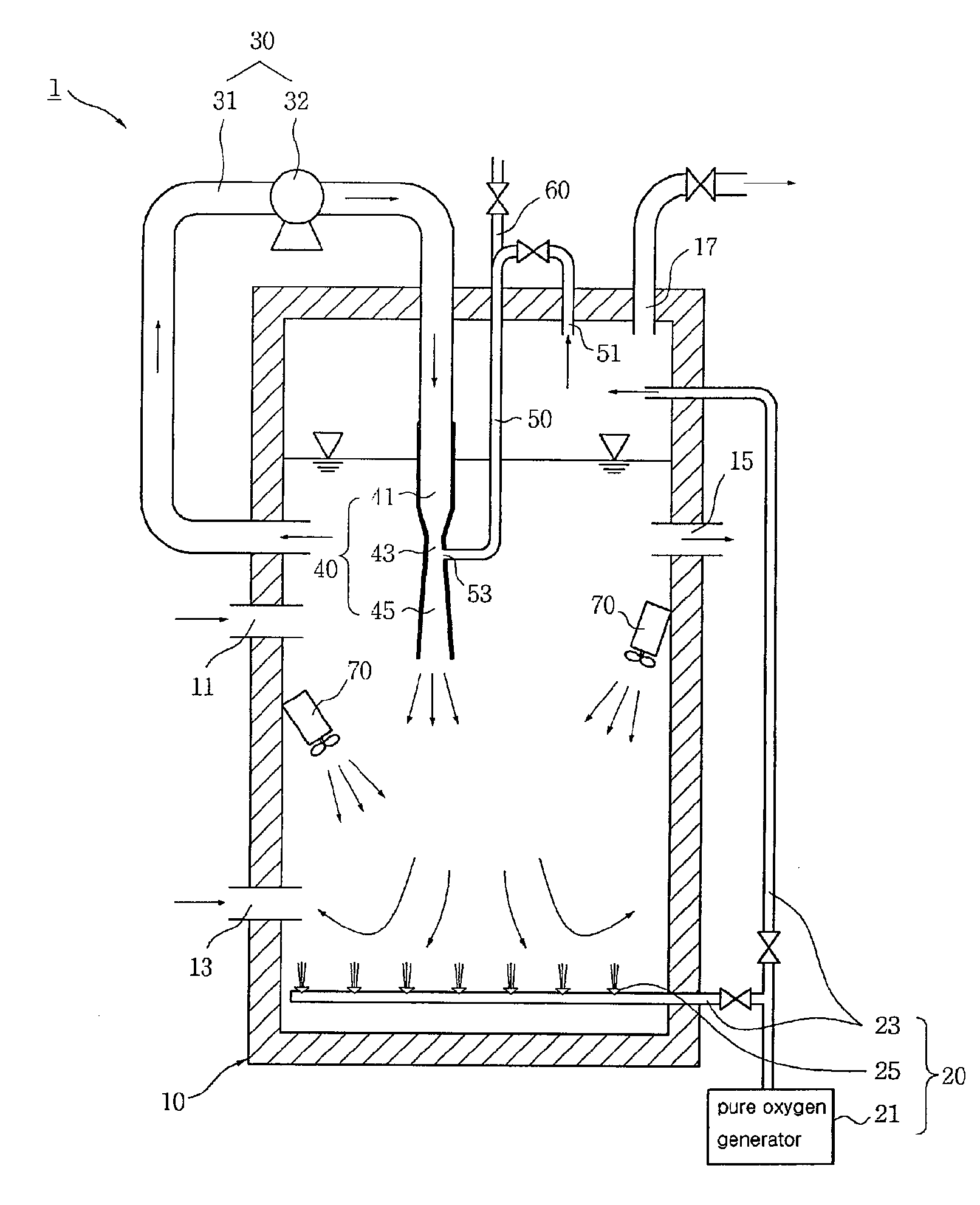
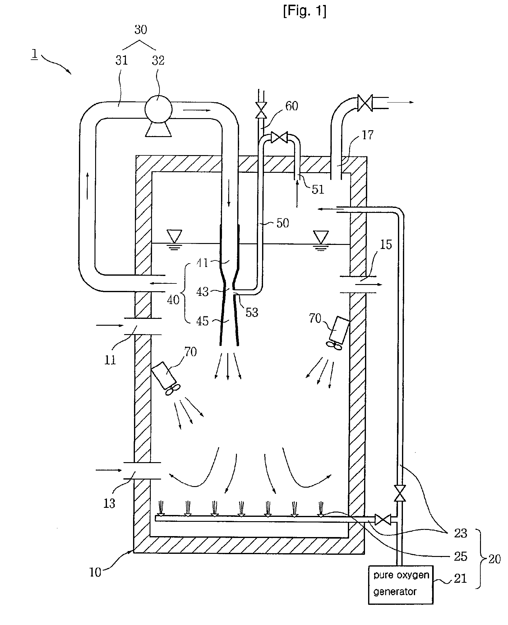
[0060]FIG. 1 is a cross-sectional view illustrating a pure oxygen aeration system for wastewater treatment according to the present invention. As shown in FIG. 1, the pure oxygen aeration system 1 comprises an aeration tank 10 for providing space in which aeration is performed, a pure oxygen supply device 20 for supplying pure oxygen to the aeration tank 10, a mixed liquor circulation device 30 for circulating mixed liquor in the aeration tank 10, a high-speed jet injection device 40 for rapidly jetting the mixed liquor, circulated by the mixed liquor circulation device 30, to the lower part of the aeration tank 10, and an oxygen suction pipe 50 for sucking in the oxygen remaining in the headspace of the aeration tank 10 (hereinafter, referred to as “headspace oxygen”) and reinjecting the headspace oxygen into the middle of the water in the aeration tank 10.

[0061]The aeration tank 10 has a structure which is completely sealed, and has a wastewater inlet hole 11 and an activated slud...

second embodiment

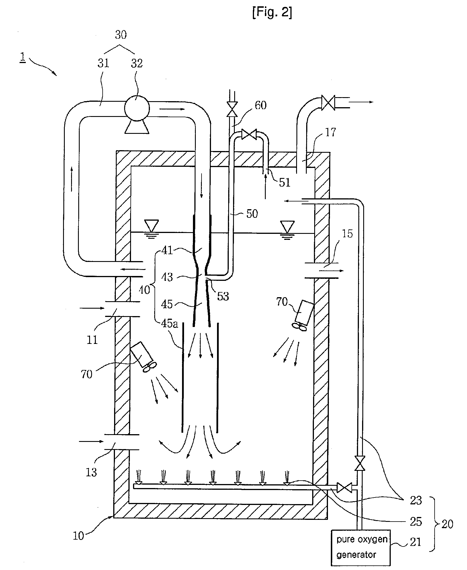
[0094]The high-speed jet injection device 40 of the pure oxygen aeration system 1 for wastewater treatment according to the present invention comprises an inlet pipe 41 for discharging mixed liquor transferred from a mixed liquor circulation pipe 31 at high speed, and a guide pipe 45a for guiding the mixed liquor, discharged from the inlet pipe 41, to the lower part of the aeration tank 10. Further, an oxygen pipe 50 is disposed in the inlet pipe 41. That is, the high-speed jet injection device 40 is a two-phase nozzle type.

[0095]The inlet pipe 41 is connected to the mixed liquor circulation pipe 31, and has a throat outlet 43 which is directed toward the lower part of the aeration tank 10 and has a diameter smaller than that of the inlet pipe 41. The guide pipe 45a concentrically surrounds the throat outlet 43 of the inlet pipe 41 and extends to the lower part of the aeration tank 10.

[0096]On the other hand, the oxygen suction pipe 50 has an oxygen suction hole 51 disposed above th...

third embodiment

[0102]In the pure oxygen aeration system 1 for wastewater treatment according to the present invention, the oxygen suction pipe 50 has an oxygen suction hole 51 disposed in the space above the surface of the water in the aeration tank 10, and has an oxygen discharge end 53 disposed near the discharge end area of the throat outlet 43 of the inlet pipe 41.

[0103]The oxygen suction pipe 50 can also be opened and closed by the manipulation of valves, and the air suction pipe 60 can be connected to an area of the oxygen suction pipe 50 with opening and closing mechanism, like the first embodiment and the second embodiment.

[0104]The pure oxygen aeration system having the above described connection structure of the oxygen suction pipe 50, according to the third embodiment, can sufficiently dissolve pure oxygen in the mixed liquor, in which contaminants and microbes are mixed, using the high discharge speed of the mixed liquor occurring near the throat outlet 43 of the inlet pipe 41 and the ...


PUM

PropertyMeasurementUnit
lengthaaaaaaaaaa
speedaaaaaaaaaa
diameteraaaaaaaaaa

Abstract

Disclosed is a pure oxygen aeration system for wastewater treatment, which biologically treats wastewater using microbes of activated sludge in an aeration tank. The pure oxygen aeration system comprises a pure oxygen supply device including a pure oxygen generator and at least one oxygen supply pipe extending from the pure oxygen generator and directed toward the internal space of the aeration tank, a high-speed jet injection device installed in the aeration tank, a mixed liquor circulation device for circulating and introducing the mixed liquor in which microbes of activated sludge, wastewater and pure oxygen are mixed, into the aeration tank through the high-speed jet injection device, and an oxygen suction pipe for sucking in the oxygen remaining in the headspace of the aeration tank and reintroducing the sucked oxygen into the water in the aeration tank. The present invention provides a pure oxygen aeration system for wastewater treatment which is economical, increases an oxygen utilization efficiency, secures easily the required land, saves the expense and can maintain an optimum level of dissolved oxygen and discharge smoothly and rapidly harmful gases.

Description

TECHNICAL FIELD[0001]The present invention relates to a pure oxygen aeration system for wastewater treatment, and more particularly to a pure oxygen aeration system for wastewater treatment having an improved structure, which can facilitate the supply of pure oxygen to an aeration tank and the oxygen transfer in the aeration tank.BACKGROUND ART[0002]A general wastewater treatment method comprises a pretreatment process for screening solids, such as suspended solids, sand and clay, a biological decomposition process for removing and decomposing organic matter and nutrients in wastewater using activated sludge, and a solid-liquid separation process for settling the activated sludge, in which microbes are increased in numbers during the biological decomposition process, decanting treated water, and returning the settled activated sludge to a biological decomposition process tank.[0003]The biological decomposition process is the most important of the processes for wastewater treatment, ...

Claims


Application Information

Patent Timeline
Patent Type & Authority Applications(United States)
IPC IPC(8): C02F3/20
CPCB01F3/04269B01F3/0446B01F3/04609B01F5/0206B01F5/0212C02F3/26B01F5/106B01F2003/04879C02F3/1294C02F3/20B01F5/0413Y02W10/10B01F23/23124B01F23/232B01F23/23341B01F23/237612B01F25/211B01F25/21B01F25/312B01F25/53C02F2201/002B01F23/2326
Inventor LEE, JAI-HUN
Owner LEE JAI HUN
Why Eureka
Try Eureka