Internal combustion engine adjusting the rotation angle of a camshaft with respect to a crankshaft

a technology of camshaft and crankshaft, which is applied in the direction of machines/engines, mechanical devices, couplings, etc., can solve the problems of unintentional omission of annular disks, unacceptably impossible movement of drive units of devices, and damage to internal combustion engines. achieve the effect of high prestressing for

Inactive Publication Date: 2005-01-25
SCHAEFFLER TECH AG & CO KG
View PDF13 Cites 23 Cited by
  • Summary
  • Abstract
  • Description
  • Claims
  • Application Information

AI Technical Summary

Benefits of technology

Therefore, in both embodiments described, the device which has been designed in accordance with the invention for altering the control times of gas exchange valves of an internal combustion engine, in particular the means for hydraulically adjusting the rotation angle of a camshaft with respect to a crankshaft, has the advantage over the prior art that the insertion of an additional annular disk, which is provided with a coating which increases friction, into the clamping joint between the output unit of the device and the end side of the camshaft provides an inexpensive way of significantly reducing the prestressing force of the central securing bolt which is required for play-free torque transmission from the drive unit to the camshaft. This also avoids the increased mechanical load on the output unit, with the associated disadvantageous effects for the device, which results from the high prestressing force which has hitherto been required. Furthermore, in both embodiments, the additional annular disk includes, as an indispensable part of the connection between the device and the camshaft if subsequent damage is to be avoided, suitable elements which can be mechanically or visually detected and by means of which unintentional omission or the presence of the annular disk can be reliably checked during or after mounting of the device on the camshaft. However, the range of possible applications for annular disks of this type is not restricted just to the connection between a camshaft adjustment device and a camshaft, but rather can also be extended to general axial clamping connections between a shaft or hub and a component which is to be flanged on, for example sprockets, pulleys or gearwheels.
for the device, which results from the high prestressing force which has hitherto been required. Furthermore, in both embodiments, the additional annular disk includes, as an indispensable part of the connection between the device and the camshaft if subsequent damage is to be avoided, suitable elements which can be mechanically or visually detected and by means of which unintentional omission or the presence of the annular disk can be reliably checked during or after mounting of the device on the camshaft. However, the range of possible applications for annular disks of this type is not restricted just to the connection between a camshaft adjustment device and a camshaft, but rather can also be extended to general axial clamping connections between a shaft or hub and a component which is to be flanged on, for example sprockets, pulleys or gearwheels.

Problems solved by technology

However, since the additional annular disk represents an indispensable component of the connection between the device and the camshaft if the internal combustion engine is to function without problems, it must be possible to detect in a suitable way that this disk has been either unintentionally omitted or that it is present.
Otherwise the reduced prestressing force of the securing bolt may cause undesirable rotation of the device on the camshaft and under unfavorable circumstances, damage to the internal combustion engine.
To check if the metal disk is present, the device is operatively connected to a stop face, which is arranged opposite its drive unit in the direction facing the camshaft, such that when the device is bolted to the camshaft by the central securing bolt, unintentional omission of the annular disk can be mechanically detected because the device becomes jammed against the stop face.
Therefore, omission of the additional annular disk inevitably eliminates the functionally important distance between the device and the opposite stop face after the device has been mounted on the camshaft, and causes recognition, without further tools, that the drive unit of the device, which is otherwise pivotably moveable, becomes unacceptably impossible to move.

Method used


Image

  • Internal combustion engine adjusting the rotation angle of a camshaft with respect to a crankshaft
  • Internal combustion engine adjusting the rotation angle of a camshaft with respect to a crankshaft
  • Internal combustion engine adjusting the rotation angle of a camshaft with respect to a crankshaft

Examples


first embodiment

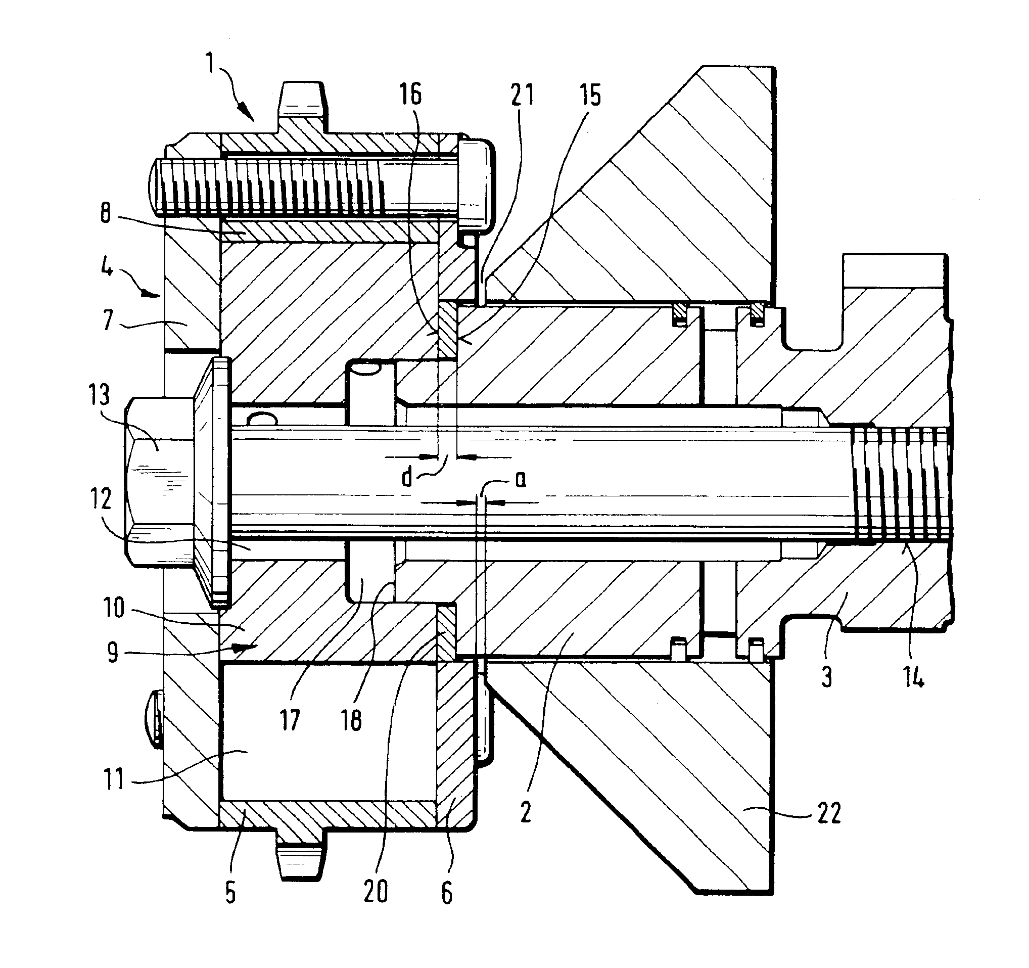
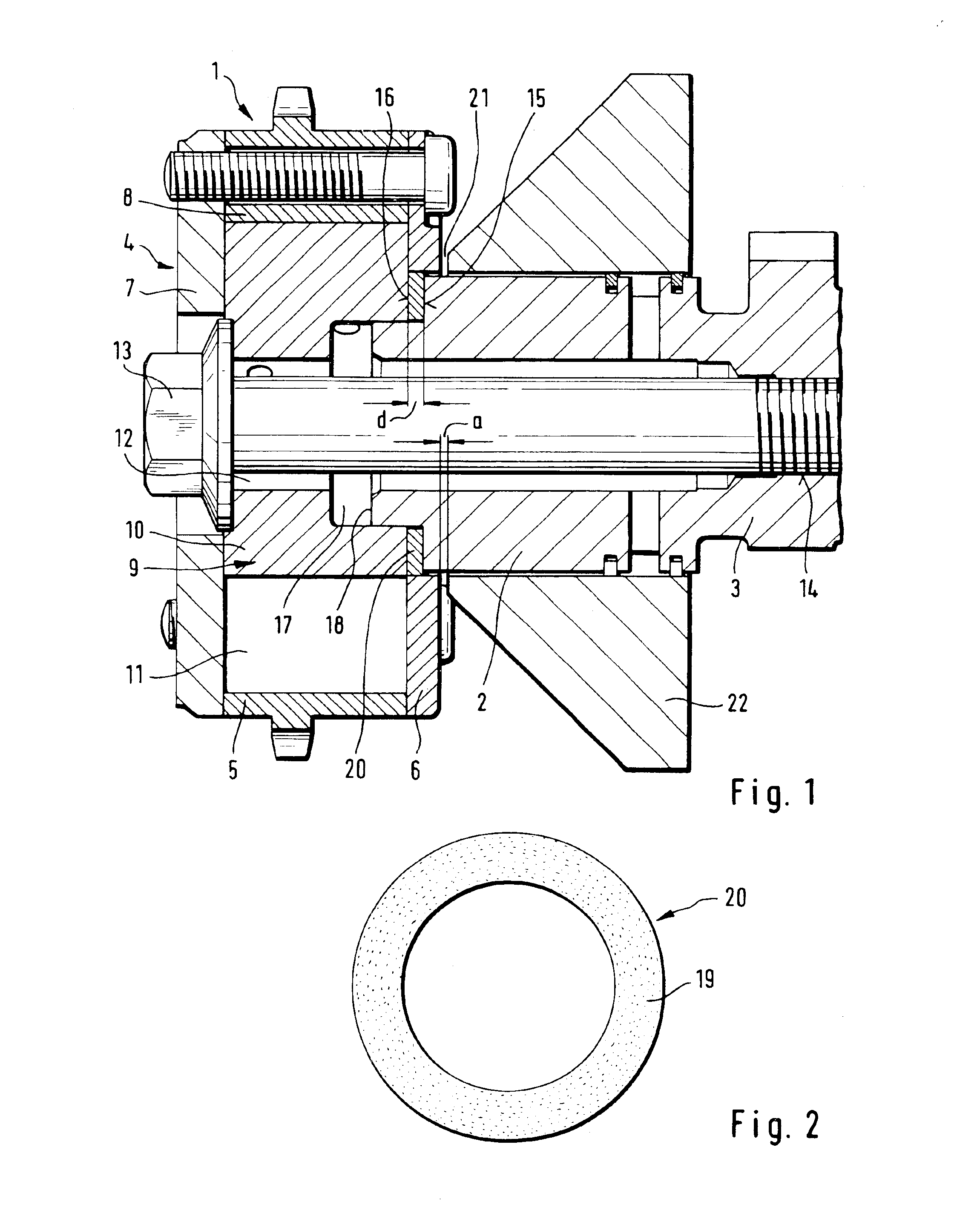
In FIGS. 1 and 2, the additional annular disk 20, comprises a metal disk which is coated on both opposite side faces with aluminum-titanium dioxide. The disk is inserted like a standard washer into the clamping joint between the output unit 9 of the device 1 and the end side 15 of the device 3. As a check that this annular disk 20 is present, the disk has a defined thickness d, while a stop face 21 is arranged opposite the drive unit 4 of the device 1, at a distance a which is selected to be less than the thickness d of the annular disk 20, in the direction which faces the camshaft. The stop face is defined by a further engine component 22, which in FIG. 1 is a pressure-medium distributor of the device 1. When the device 1 is being bolted to the camshaft 3 by the central securing bolt 13, unintentional omission of the annular disk 20 may be mechanically detected when the device 1 becomes jammed against the stop face 21.

second embodiment

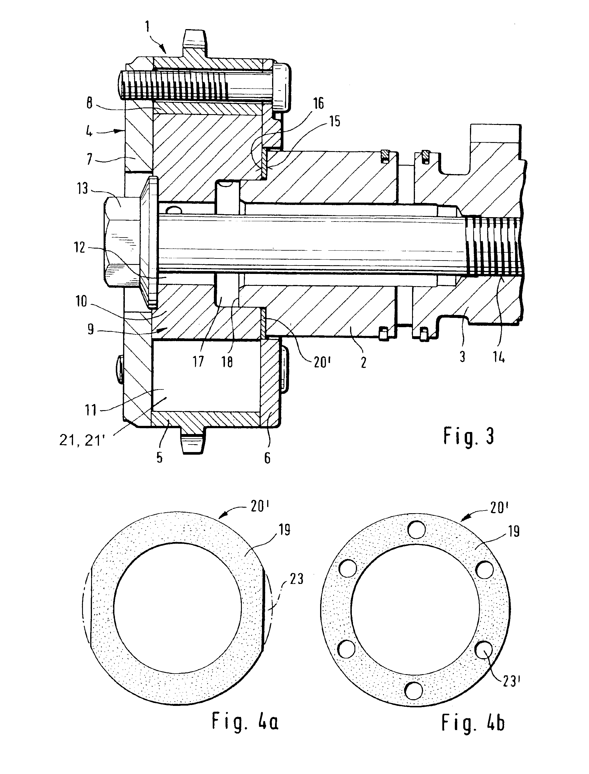
In the device 1 in FIG. 3, an additional annular disk 20′ in FIG. 4a or 4b, comprises a plastic film or metal foil with a coating 19 comprised of diamond dust disposed on both opposite side faces. To check if this annular disk 20′ is present when the device 1 is being bolted to the camshaft 3, the annular disk 20′ has various visually detectable features, which make it stand out from adjacent components or make it visually noticeable. In the first annular disk 20′ variant in FIG. 4a, these exemplary visual features are a reflection layer mixed into the coating 19 and recesses 23 machined into the side faces shaped as parallel notches. In the second annular disk 20′ variant FIG. 4b, the optical features are an indicator color, which is mixed into the coating 19, and a plurality of recesses 23′, which are machined into the side faces in the form of stamped holes distributed uniformly around the circumference. Through the recesses 23′, as for the recesses 23 in the first disk variant 2...


PUM


Abstract

A device for hydraulically adjusting the rotation angle of a camshaft with respect to a crankshaft of an internal combustion engine: A drive unit connected to a crankshaft and an output unit connected to a camshaft, having radially extending, axially facing sides secured by the pre-stressing force of a central securing bolt. The drive unit is rotably mounted to the output unit and they are so connected that at least two hydraulic pressure chambers transmit relative rotation forces. An annular disk with coating on opposite sides increases the frictional force between the end face of the output unit which faces the camshaft and the end of the camshaft and enables reduction of the pre-stressing force on the bolt. The character of visually detectable elements on the disk enable detection of the presence or absence of the disk.

Description

FIELD OF THE INVENTIONThe invention relates to a device for altering the control times of gas exchange valves of an internal combustion engine which can be implemented particularly advantageously on a means for hydraulically adjusting the rotation angle of a camshaft with respect to a crankshaft, and particularly relates to eliminating prestressing force on a bolt that fastens the drive and output units on the respective shafts.BACKGROUND OF THE INVENTIONA device of this type is already known from EP 0 896 129 A1. This device in principle is designed as a hydraulic actuating drive which can be controlled as a function of various operating parameters of the internal combustion engine. It is arranged at the drive-side end of a camshaft mounted in the cylinder head of the internal combustion engine. It substantially comprises a drive unit, which is drive-connected to a crankshaft of the internal combustion engine, and an output unit, which is connected in a rotationally fixed manner to...

Claims


Application Information

Patent Timeline
Patent Type & Authority Patents(United States)
IPC IPC(8): F01L1/00F01L1/46F01L1/344F01L1/34
CPCF01L1/34F01L1/46F01L1/3442Y10T74/2102
Inventor KOHRS, MIKE
Owner SCHAEFFLER TECH AG & CO KG
Why Eureka
Try Eureka