Method for operating a fuel injection system

a fuel injection system and fuel injection technology, applied in the direction of electrical control, process and machine control, instruments, etc., can solve the problems of minimizing the disadvantages of internal combustion engine operation, low complexity of carrying out the method, etc., to improve the accuracy of the method, improve the method accuracy, and improve the effect of method accuracy

Inactive Publication Date: 2014-04-10
ROBERT BOSCH GMBH
View PDF21 Cites 20 Cited by
  • Summary
  • Abstract
  • Description
  • Claims
  • Application Information

AI Technical Summary

Benefits of technology

[0013]Additionally, it may be provided that a fuel temperature and/or a fuel type may also be considered when the pressure prevailing in the pressure accumulator is inferred from the slope. These variables may, for example, be used as parameters in the “connection” described in the following, whereby the accuracy of the method may be improved. Frequently, the fuel temperature and/or the fuel type is, however, not known in the control and/or regulating device, since these variables are comparably complex when it comes to being ascertained. Moreover, it may not be possible to infer the fuel temperature and/or the fuel type from the mentioned slope of the curve, since the fuel pressure and the pressure sensor are also checked according to the present invention. The method according to the present invention may work in principle independently of the fuel temperature and the fuel type. If these variables are known, however, for example by being measured, they may potentially further improve the accuracy of the method.
[0014]Furthermore, it may be provided that a connection is ascertained between the slope of the curve, which links the pressure difference in the pressure accumulator during a fuel injection to the injected fuel quantity, during a test operation (e.g., in a laboratory) and/or in a new condition of the internal combustion engine and/or in a new condition of the pressure sensor, and this connection is preferably stored in the form of equations, tables, characteristic curves, characteristic maps, and/or models. Thus, the example method includes a first method step in the test operation, and a second method step in a subsequent “normal” operation of the internal combustion engine, or of a motor vehicle driven by the internal combustion engine. During the test operation, a connection is ascertained from ascertained pressure differences of the fuel pressure in the pressure accumulator and the associated injection quantities in each case and the associated actually measured values of the fuel pressure. This connection includes, ...

Problems solved by technology

Therefore, the complexity for carrying out the method may remain particularly low, possibly disadvantageous effects on the operation of the internal combustion engine being minimized.
Freq...

Method used


Image

  • Method for operating a fuel injection system
  • Method for operating a fuel injection system
  • Method for operating a fuel injection system

Examples


Embodiment Construction

[0024]The same reference numerals are used for functionally equivalent elements and variables in all figures, even in different specific embodiments.

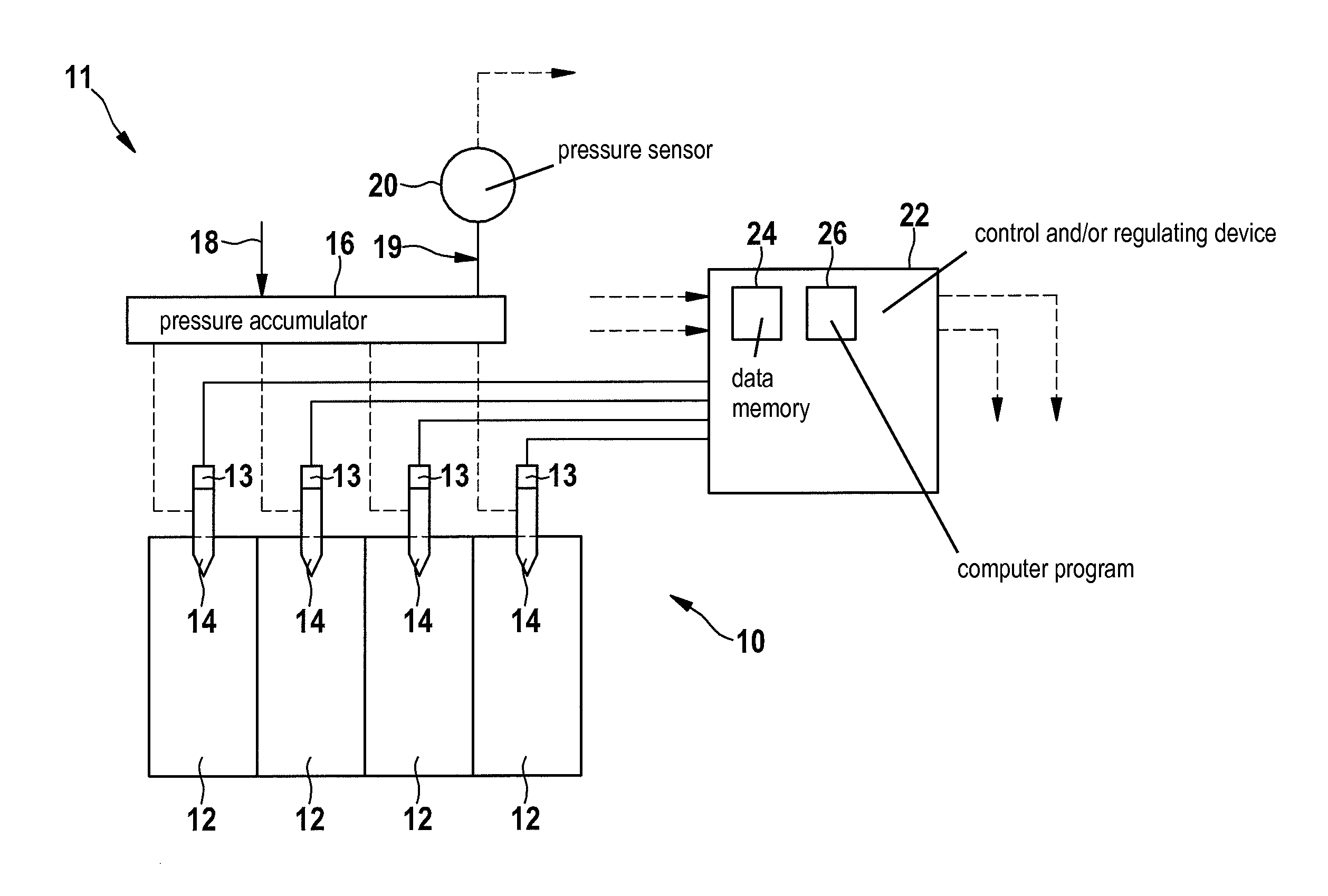
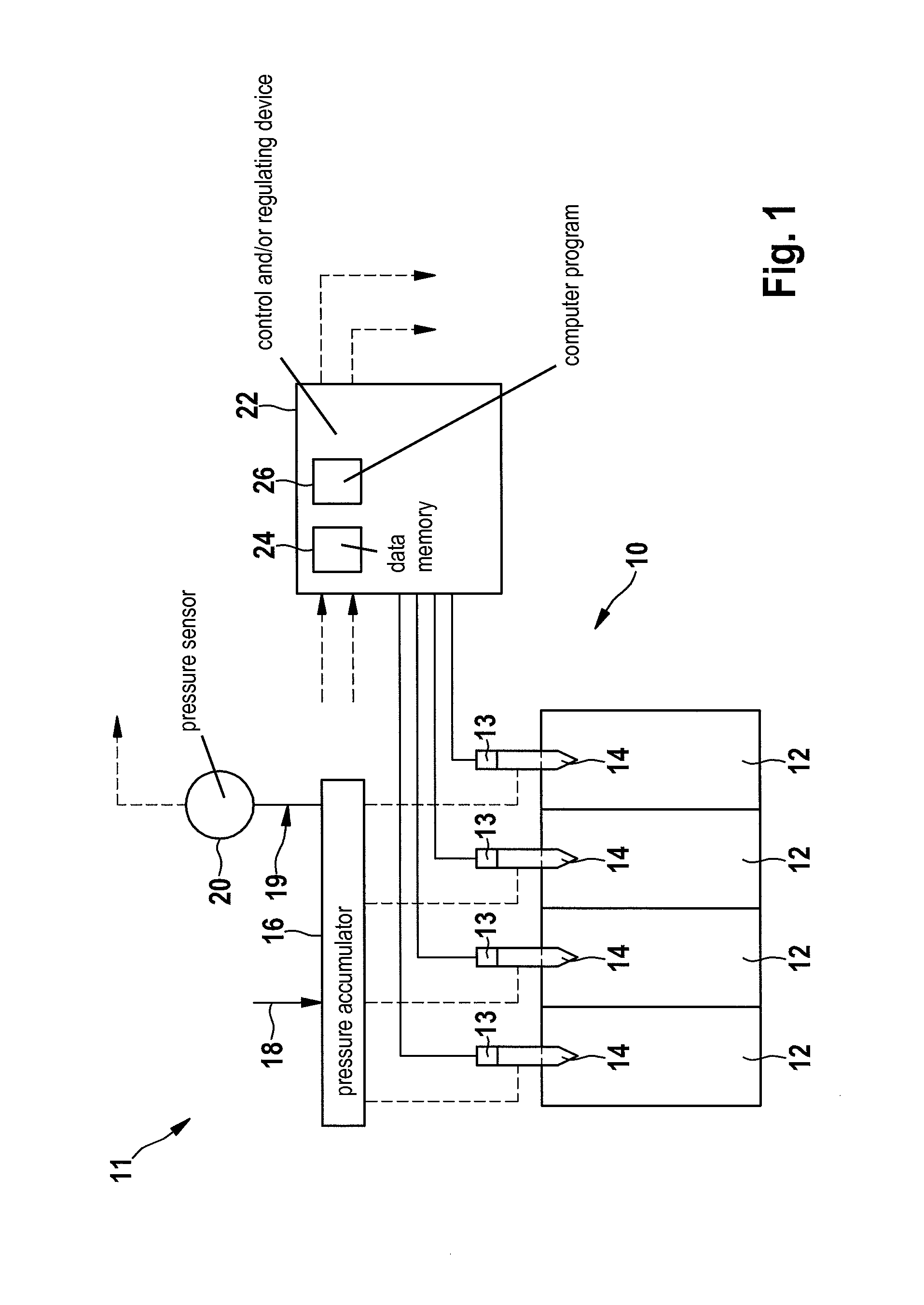
[0025]FIG. 1 shows a simplified schematic view of a fuel system 11 (“fuel injection system”) for an internal combustion engine 10 in the present case having four combustion chambers 12 (“cylinders”) and associated injectors 14 (“fuel injection systems”) for injecting fuel. For example, internal combustion engine 10 is a gasoline engine or a diesel engine of a motor vehicle (not illustrated in the drawing). Injectors 14 may each be actuated by an electromagnetic actuator 13. Alternatively, electromagnetic actuator 13 may also be designed as a piezoelectric actuator 13.

[0026]In the figure, a pressure accumulator 16 (high-pressure accumulator, “rail”) is illustrated above injectors 14, the pressure accumulator being supplied with fuel from a high-pressure line 18. A fuel pressure 19 (“rail pressure”) in pressure accumulator 16 is monitored...


PUM


Abstract

A fuel injection system for an internal combustion engine in which pressurized fuel is made available in a pressure accumulator and a fuel pressure prevailing in the pressure accumulator is ascertained with the aid of a pressure sensor and in which the fuel enters a combustion chamber of the internal combustion engine through at least one fuel injection device. A slope of a curve, which links a pressure difference in the pressure accumulator during a fuel injection to an injected fuel quantity, is ascertained and the fuel pressure prevailing in the pressure accumulator is inferred from the slope.

Description

CROSS REFERENCE[0001]The present application claims the benefit under 35 U.S.C. §119 of German Patent Application No. DE 102012218176.8 filed on Oct. 5, 2012, which is expressly incorporated herein by reference in its entirety.FIELD[0002]The present invention relates to a method for operating a fuel injection system, as well as to a control and / or regulating device, a computer program, and a storage medium.BACKGROUND INFORMATION[0003]In some conventional internal combustion engines, an operating state and / or values of variables important for the operation may be monitored with the aid of a so-called on board diagnosis. Among other things, a correctly set fuel pressure in a pressure accumulator of a fuel system of the internal combustion engine is important. The fuel pressure is frequently ascertained with the aid of a pressure sensor (“rail pressure sensor,” RPS). In order to check or monitor the pressure sensor for proper functioning, it is, for example, possible to situate a secon...

Claims


Application Information

Patent Timeline
IPC IPC(8): F02D41/30
CPCF02D41/30F02D41/2467F02D41/402F02D41/403F02D2200/0602F02D2200/0616Y02T10/40F02D41/3076
Inventor EMPACHER, LARSZIEHER, RENEOLBRICH, STEPHANSCHENK, MICHAEL
Owner ROBERT BOSCH GMBH
Why Eureka
Try Eureka