
Firearm sling and method of making

a technology of slings and firearms, applied in the field of slings, can solve the problems of substantial stress, loss of mounting hardware and buckles, and affecting the safety of the sling, and achieve the effect of preventing the loss of connecting members and more quiet operation

Inactive Publication Date: 2006-09-21
ESCH BRIAN
View PDF34 Cites 36 Cited by
  • Summary
  • Abstract
  • Description
  • Claims
  • Application Information

AI Technical Summary

Benefits of technology

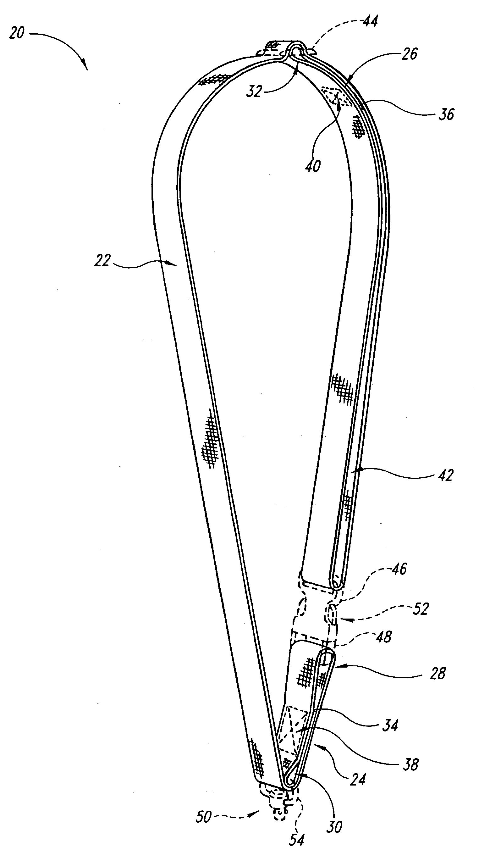
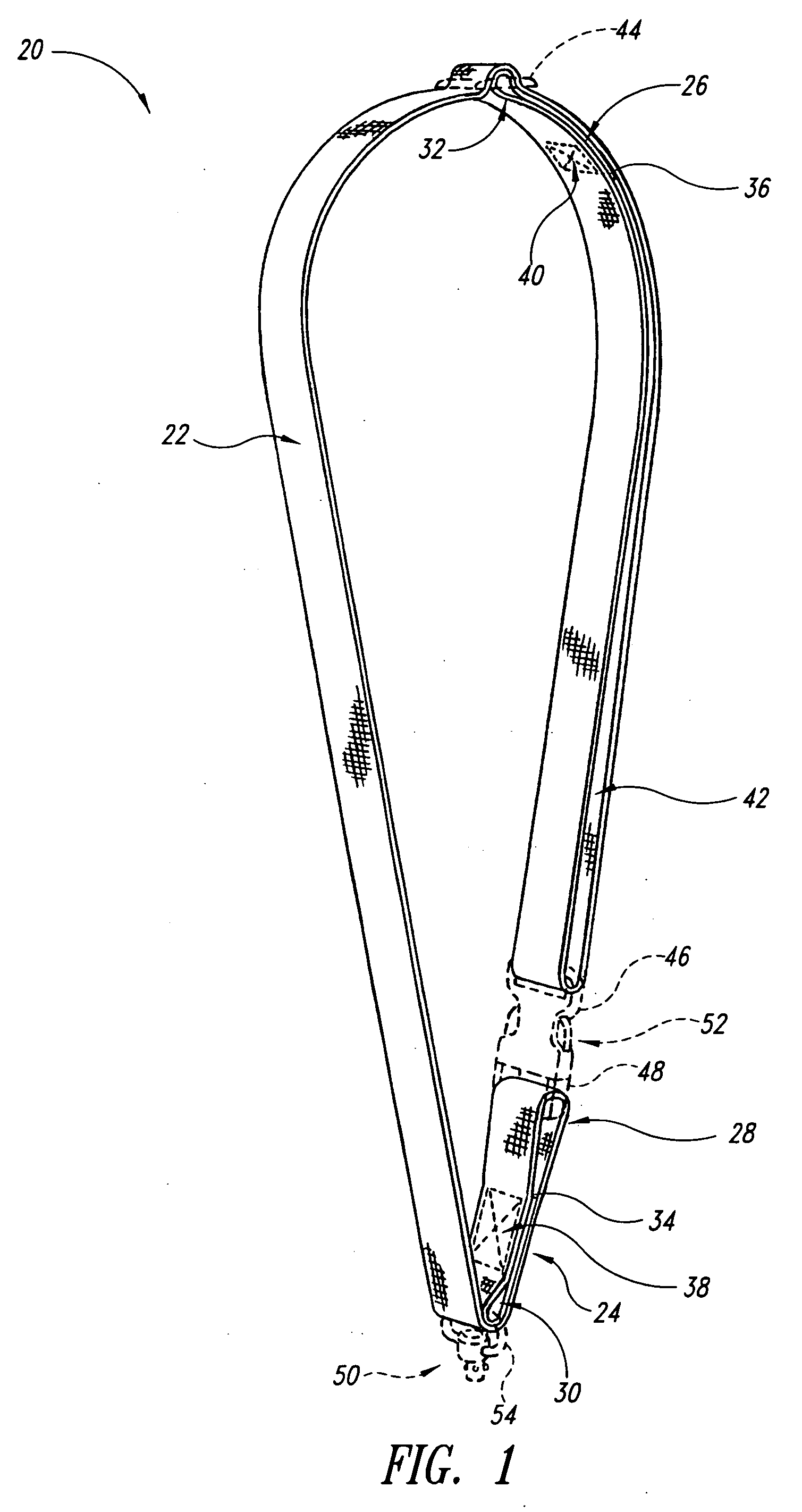
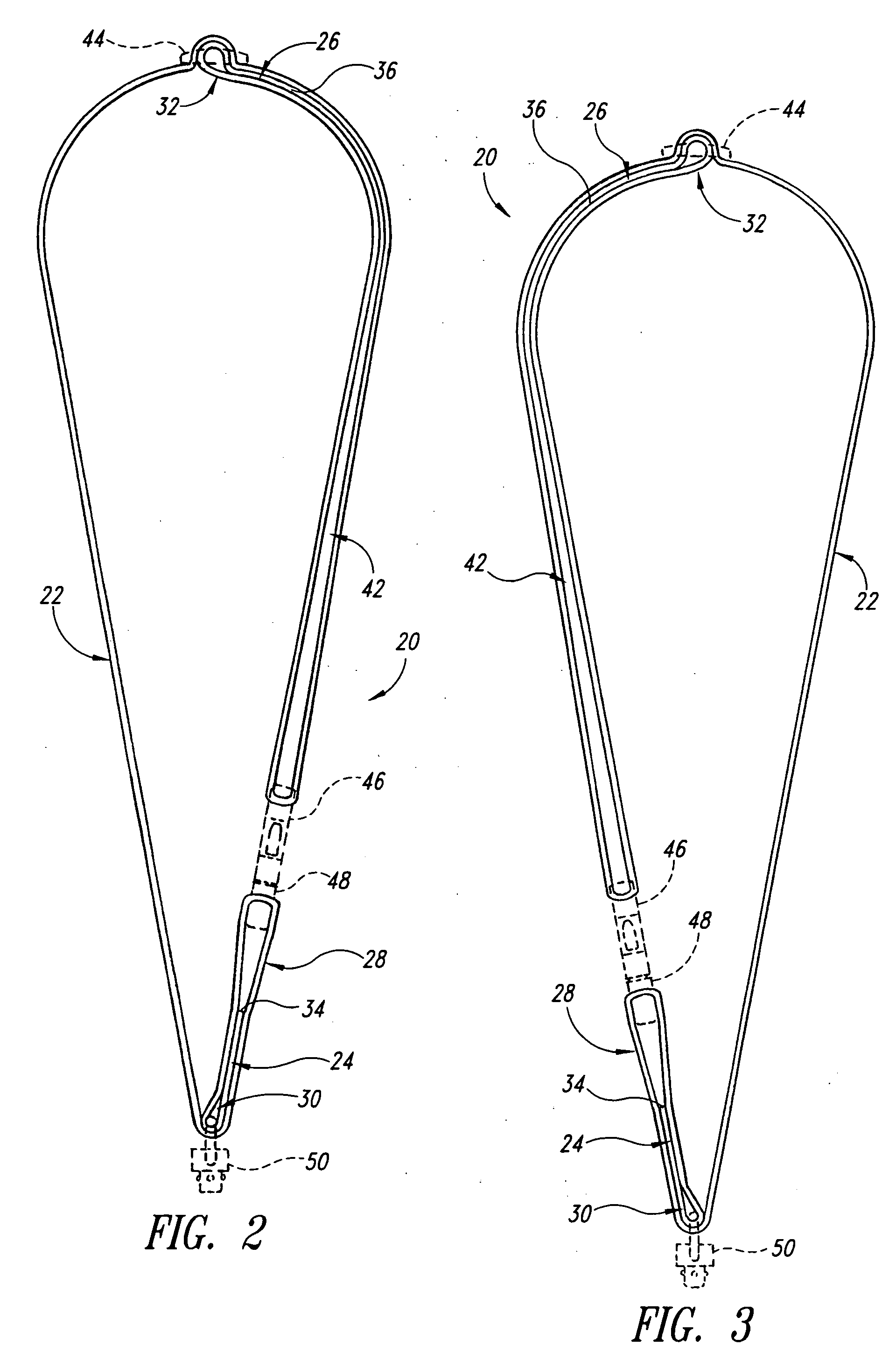
[0010] The disclosed embodiments of the present invention are directed to a sling formed of a strap and a corresponding weapon system having a single attachment point in which the strap has a permanent, durable double loop at one end to reinforce the sling and to provide more quiet operation and prevent loss of connecting members.
[0017] As will be readily appreciated from the foregoing, the sling of the present invention provides a one-point tactical sling system utilizing quick-release buckles and a permanently-secured swivel connector that provides unmatched freedom of movement, reliable weapon indexing, smooth weapon transitions, superior weaponry tension, and security. Loss of buckles and swivel mounts is reduced by permanent attachment to the loops, and quiet operation is promoted by separation of mechanical elements attached to the first and second loops. In addition, enhanced strength is provided at the second loop by the extension of the strap past the second loop and through the swivel connector from which the weapon is suspended.

Problems solved by technology

One area of concern is material failure in the sling fabric such that the sling separates or fabric loops formed by the sling material come undone, causing the weapon to fall away or become lost.
A further concern is the loss of mounting hardware and buckles when releasable loops on the sling are opened.
The draw-back with this design is the substantial stress placed on the temporary loop by both the mounting ring and buckle, as well as the potential for losing the ring when undoing the sling.

Method used


Image

  • Firearm sling and method of making
  • Firearm sling and method of making
  • Firearm sling and method of making

Examples


Embodiment Construction

[0029] In the following description, certain specific details are set forth in order to provide a thorough understanding of various disclosed embodiments. However, one skilled in the relevant art will recognize that embodiments may be practiced without one or more of these specific details or with other methods, components, materials, etc. In other instances, well-known structures or components or both associated with weapon systems, slings, and straps, and other devices such as buckles, fasteners, connection members, and the like have not been shown or described in detail in order to avoid unnecessarily obscuring the illustration and description of the embodiments of the present invention.

[0030] Unless the context requires otherwise, throughout the specification and claims that follow, the word “comprise” and variations thereof, such as “comprises” and “comprising” are to be construed in an open, inclusive sense, that is, as “including, but not limited to.”

[0031] Reference through...


PUM


Abstract

A sling mount system having a mount with associated receiver for releasable connection with a swivel connector having a longitudinal axis that lies in the same plane as a longitudinal axis of a weapon and that angles downward away from the butt stock. The receptacle for the swivel connector is integrally formed in the mount to facilitate silent connection and disconnection of the swivel mount thereto.

Description

CROSS-REFERENCE TO RELATED APPLICATION [0001] This application is a continuation of U.S. patent application Ser. No. 29 / 197,103, filed Jan. 9, 2004, now pending, which application is incorporated herein by reference in its entirety.BACKGROUND OF THE INVENTION [0002] 1. Field of the Invention [0003] The present invention pertains to slings for carrying an object and, more particularly, to a sling system adapted for use with a single attachment point on firearms to provide greater strength and quieter operation in a variety of tactical environments. [0004] 2. Description of the Related Art [0005] Slings are of ancient origin, devised generally of a loop of rope, strap, or a chain for supporting a load. While its history remains unknown, the sling is in widespread use in modern times in connection with a variety of manual and mechanical uses, including baby slings, arm slings, camera slings, musical instrument slings, and weapon slings. [0006] When used manually, a properly designed sl...

Claims


Application Information

Patent Timeline
Patent Type & Authority Applications(United States)
IPC IPC(8): F41C33/00A45F3/14F41C23/02
CPCA45F3/14A45F5/02A45F2200/0591F41C23/02F41C33/001F41C33/002
Inventor ESCH, BRIAN
Owner ESCH BRIAN
Learn More