Portable screen device with dual shaft structure

Inactive Publication Date: 2006-09-21
CHOI HAE YONG
View PDF1 Cites 24 Cited by
  • Summary
  • Abstract
  • Description
  • Claims
  • Application Information

AI Technical Summary

Benefits of technology

[0015] Therefore, the present invention has been made in view of the above and/or other problems, and it is an object of the present invention to provide a portable screen device in which a structure in which a component, whose performance is deteriorated as the more it is used, such as a gas spring, a gas shock absorber, or a brake lever as a necessity

Problems solved by technology

As the conventional gas spring or the coil spring is used, the performance such as the quantity of gas is decreased or the elasticity of the coil spring is deteriorated.
Actually, as a result of checking the screen devices returned by customers, malfunction caused by the coil spring or the gas spring accounts for more than 40 percent.
In addition, there is a plurality of the gas springs or the coil springs as the height-maintaining device, the conventional movable screen device is heavy and its volume is increased.
However, since in this movable screen device the right and t

Method used


Image

  • Portable screen device with dual shaft structure
  • Portable screen device with dual shaft structure
  • Portable screen device with dual shaft structure

Examples


Example

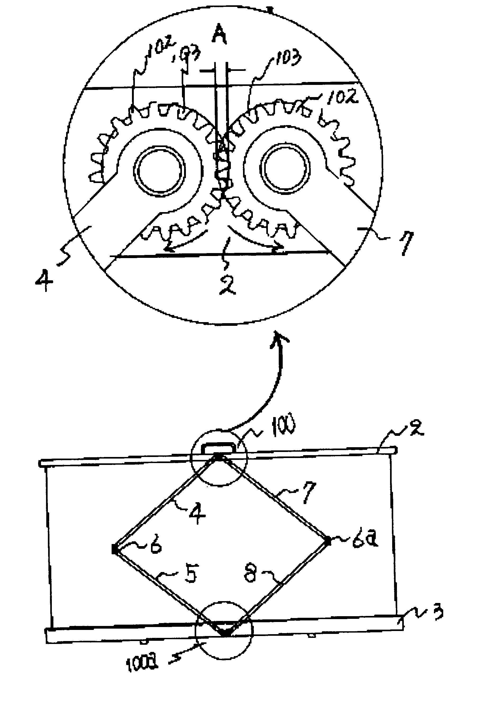
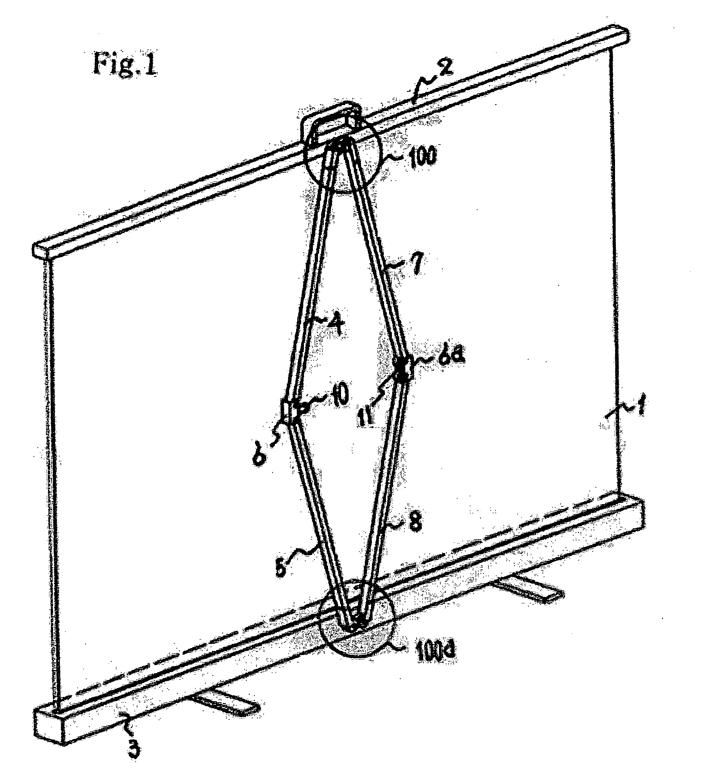
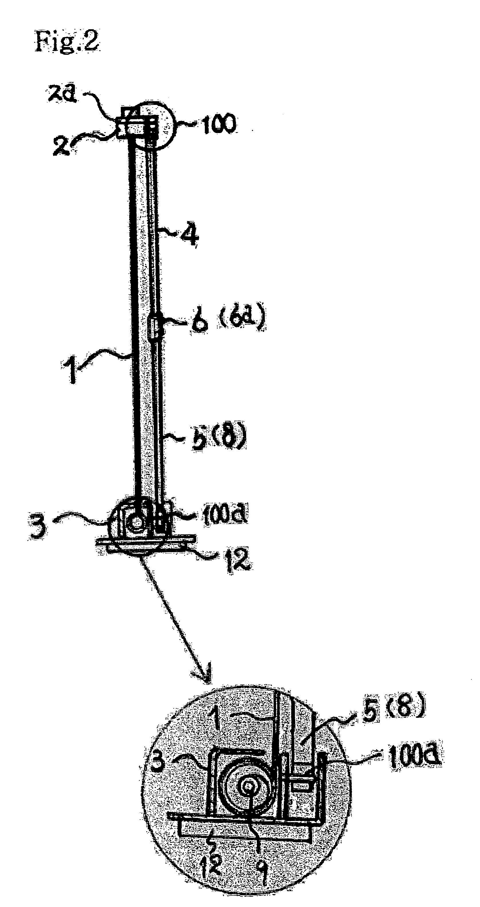
[0025] A portable screen device having a dual shaft structure according to a preferred embodiment of the present invention, as shown in FIGS. 1, 2, 3, 4, 5, 6, and 7, includes an upper rod 2 installed in the upper side of the portable screen device, a spring rotation rod 9 installed inside a lower frame 3 and having a spring 3a installed as shown in FIG. 2, and a screen 1 connected to the upper rod 2 and the spring rotation rod 9 to be rolled in and out according to the rotation of the spring rotation rod 9.

[0026] When the upper rod 2 is pulled up, since the spring 3a in the spring rotation rod 9, as shown in FIG. 2, is wound in, the screen 1 and the upper rod 2 are pulled down due to gravity, if the upper rod 1 is free, the spring rotation rod 9 is rotated by the spring 3a to automatically wind the screen 1.

[0027] As shown in FIGS. 3 and 4, an upper adjusting device 100 is installed in the upper side of the upper rod 2 such that an upper left support 4 and an upper right support ...


PUM


Abstract

A portable screen device having a dual shaft structure is disclosed. A left and a right rotation shafts are installed to an upper rod and the center of a lower frame of a screen in the horizontal direction and are connected to a left and a right supports. The rotation shafts are engaged with each other by a single adjusting device. When the screen moved up, the elasticity of the screen is held by left and right elastic wheels such that height of the screen is maintained. A magnet and a magnetic substance contact each other and are separated from each other at the central portions of the left and right supports. Due to rotation of a rotation rod installed in the intermediate portion of the supports, the screen moves up and down. Therefore, volume and weight of the portable screen device are reduced and the stability is increased.

Description

BACKGROUND OF THE INVENTION [0001] 1. Field of the Invention [0002] The present invention relates to a portable screen device for displaying an image projected from a projector, in particularly, to a portable screen device capable of moving a screen up and down when a screen is maintained horizontal by dual rotation shafts, maintaining the height of the screen by substituting a structure using a gas spring or a coil spring with a structure of right and left eccentric rotation shafts, having a remarkably reduced volume and weight, and increased stability. [0003] 2. Description of the Related Art [0004] In portable screen devices, since the less a volume is the more convenient it is to carry and the lighter it is the more practical, a structure for reducing volume and weight is a very important development and goal. [0005] As structures of a conventional portable screen device, a structure, in which a screen rolled around a spring rotation shaft is accommodated in an accommodating cas...

Claims


Application Information

Patent Timeline
IPC IPC(8): G03B21/56
CPCG03B21/58F04B33/00F04B39/0022F04B39/10
Inventor CHOI, HAE-YONG
Owner CHOI HAE YONG
Why Eureka
Try Eureka