Scanner for optical storage media

a technology for scanning optical storage media and optical storage media, which is applied in the field of scanning optical storage media, can solve the problems of cost saving, and achieve the effect of preventing damage to optical storage media and to the objective lens and producing easily

Inactive Publication Date: 2006-09-21
THOMSON LICENSING SA
View PDF3 Cites 7 Cited by
  • Summary
  • Abstract
  • Description
  • Claims
  • Application Information

AI Technical Summary

Benefits of technology

[0006] One object of the invention is to propose an optical scanner in which damage to the optical storage medium and to the objective lens is prevented, and which can be produced easily.

Problems solved by technology

At the same time, no additional parts are required for protection of the objective lens, thus resulting in cost savings.

Method used


Image

  • Scanner for optical storage media
  • Scanner for optical storage media
  • Scanner for optical storage media

Examples


Embodiment Construction

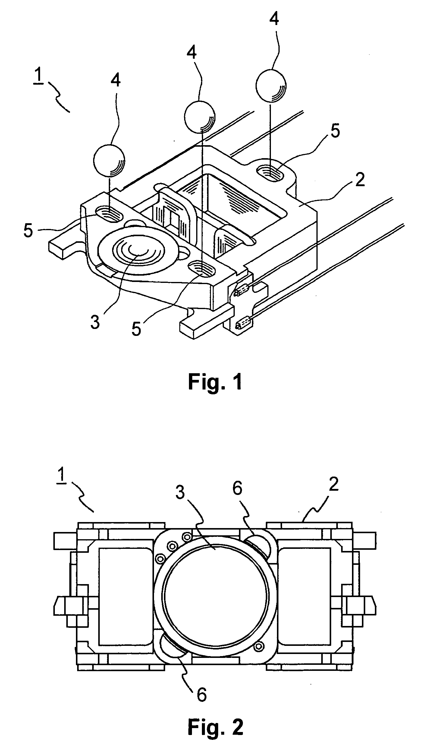
[0016]FIG. 1 shows a scanner 1 for optical storage media according to the prior art. The scanner 1 has a lens holder 2 for holding an objective lens 3, which is mounted in an opening in the lens holder 2. Three balls 4 composed of silicone rubber, which are pressed into associated cutouts 5 in the lens holder 2, act as protection against collisions between the objective lens 3 and an optical storage medium (not illustrated). Further elements of a scanner are known to those skilled in the art, and will not be explained any further here.

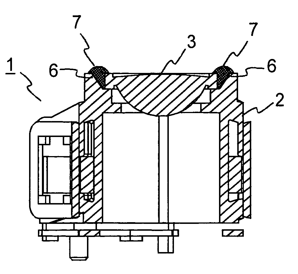
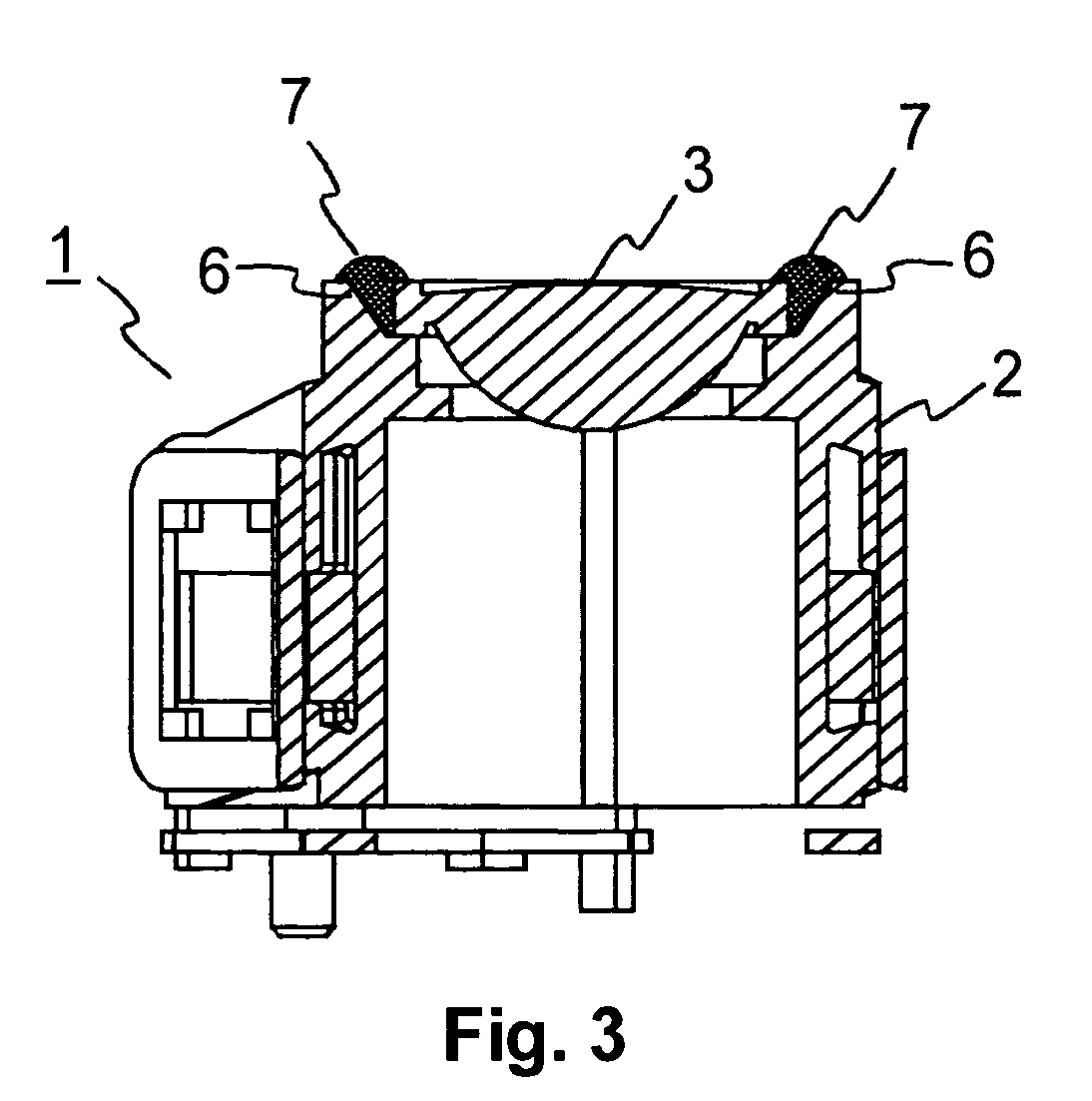
[0017]FIG. 2 shows a scanner 1 according to the invention for optical storage media. In this case as well, an objective lens 3 is mounted in an opening in a lens holder 2. The mounting takes place by means of a soft adhesive, which is inserted into funnel-shaped adhesive pockets 6. The adhesive pockets 6 are designed such that they extend to the edge of the objective lens 3. If the adhesive pockets 6 are filled with a small amount of excess adhesive, ...


PUM

PropertyMeasurementUnit
adhesiveaaaaaaaaaa
natural frequenciesaaaaaaaaaa
massaaaaaaaaaa

Abstract

The present invention relates to a scanner for optical storage media, and to an appliance for reading from and/or writing to optical storage media which uses a scanner such as this. The invention proposes a scanner for optical storage media, having an objective lens which is mounted in a lens holder by means of an adhesive, with the adhesive being designed to provide protection for the objective lens.

Description

FIELD OF THE INVENTION [0001] The present invention relates to a scanner for optical storage media, and to an appliance for reading from and / or writing to optical storage media which uses a scanner such as this. BACKGROUND OF THE INVENTION [0002] Scanners for optical storage media, such as CDs (compact discs) or DVDs (digital versatile discs) normally use an actuator to control the spatial position of a scanning or writing beam. During reproduction from or recording on optical storage media by such an optical scanner there is a risk that a control loop for the actuator is disturbed and the actuator collides with the storage medium in an uncontrolled manner. In order to prevent an objective lens which is attached to the actuator being damaged in a collision such as this, for example by being scratched, lens protection is frequently provided. One such means of lens protection is known, for example, from JP 2003-338063. [0003] The lens protection is normally composed of a hard material...

Claims


Application Information

Patent Timeline
Patent Type & Authority Applications(United States)
IPC IPC(8): G11B11/00G11B7/12G11B7/135
CPCG11B7/1201G11B7/1374G11B7/22G11B7/121A01G13/0256A01G2013/006
Inventor BAMMERT, MICHAELSUZUKI, TSUNEOTABOR, GUNTERDUPPER, ROLF
Owner THOMSON LICENSING SA
Why Eureka
Try Eureka