Bandwidth optimization system

a technology of bandwidth optimization and optimization system, applied in the field of data communication system, can solve problems such as unsatisfactory solutions

Inactive Publication Date: 2006-09-21
CARRIER ACCESS CORP
View PDF2 Cites 48 Cited by
  • Summary
  • Abstract
  • Description
  • Claims
  • Application Information

AI Technical Summary

Problems solved by technology

Installing additional communication links 110 presents an unsatisfactory solution because it is an expensive and limited solution to the need for additional bandwidth between BTS 106 and BSC 108.

Method used


Image

  • Bandwidth optimization system
  • Bandwidth optimization system
  • Bandwidth optimization system

Examples


Embodiment Construction

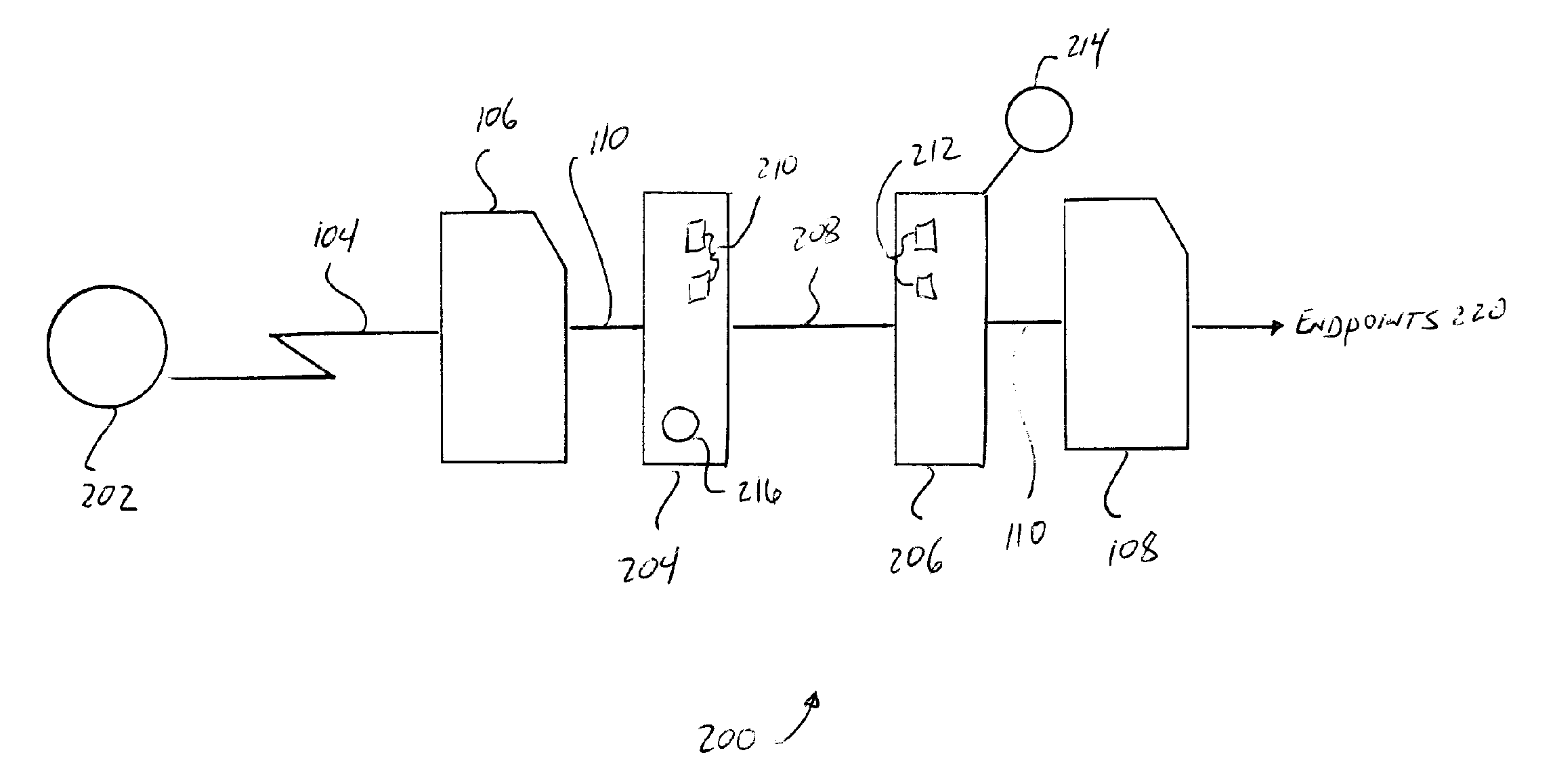
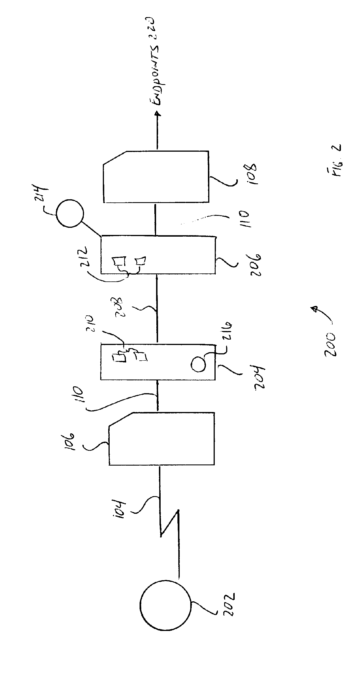
[0023] The present invention will be described with reference to FIGS. 2-12. While the present invention is described in relation to mobile communication systems transmitting, one of ordinary skill in the art will recognize on reading the disclosure that the present invention could be used in other data transmission systems using transmission protocols with portions of the data transmission being preprogrammed to particular values.

[0024] Referring now to FIG. 2, a functional block diagram of a bandwidth optimization system 200 is disclosed. For convenience, system 200 will be explained with reference to a single transmitting station 202 transmitting data. Transmitting station 202 is used generically to mean any subscriber device whether mobile or stationary, such as, for example, a remote server, a cellular telephone, a PDA, a portable computer, a desktop computer, a printer, or the like. However, the present invention will be explained with reference to a transmitting station 202 ...


PUM


Abstract

An interface between the BTS and BSC optimizes data transmitted over, for example, T1 lines to effectively increase the transmission bandwidth. The method comprises determined whether a frame of data is available for optimization. If available, the frame type is identified, the payload is extracted, and a header compiled. The payload and header are used to generate the optimized frame of data. The data stream is aggregated with non-optimized frames of data and transmitted.

Description

FIELD OF THE INVENTION [0001] The present invention relates to data communication systems and, more particularly, to a system that allows reduction of data that must be transferred over a communication link that in turn optimizes the bandwidth use. [0002] 1. Background of the Invention [0003] Communication networks, and particularly wireless communication networks, operate by sending information between Base Transceiver Stations (“BTS”) and Base Station Controllers (“BSC). FIG. 1 shows a typical wireless communication network 100. Wireless communication network 100 relates to cellular telephone or mobile stations 1021, 1022 to 102n, but other data communication devices could be substituted for mobile stations 102. Mobile stations 102 establish wireless communication links 104 to BTS 106. Conventionally, BTS 106 is connected to BSC 108 using wired communication links 110, such as, for example, T-1 lines, T-3 lines, T-4 lines, the E line equivalents, or the like. [0004] In operation, ...

Claims


Application Information

Patent Timeline
Patent Type & Authority Applications(United States)
IPC IPC(8): H04J3/24
CPCH04W4/18H04W92/12
Inventor MILLER, CHARLESVACHON, BERNARDNIEBERGER, MATHEW
Owner CARRIER ACCESS CORP
Why Eureka
Try Eureka