Reagent cuvette

a technology of cuvettes and cuvettes, which is applied in the direction of biochemistry equipment, biochemistry equipment and processes, instruments, etc., can solve the problems of large number of patients being unnecessarily subjected to trouble and worry of further unwarranted tests

Inactive Publication Date: 2006-09-21
ODONOVAN MICHAEL
View PDF4 Cites 11 Cited by
  • Summary
  • Abstract
  • Description
  • Claims
  • Application Information

AI Technical Summary

Benefits of technology

[0007] In one embodiment, the transfer means comprises a membrane across an opening of the second chamber, and a piercing member secured to the first chamber, whereby said second chamber membrane is pierced as the second chamber is pushed towards the first chamber

Problems solved by technology

Thus, a large number of patients may be unnecessarily subjected to the trouble and worry of further unwarranted tests beyond the point of care.

Method used


Image

  • Reagent cuvette
  • Reagent cuvette
  • Reagent cuvette

Examples


Embodiment Construction

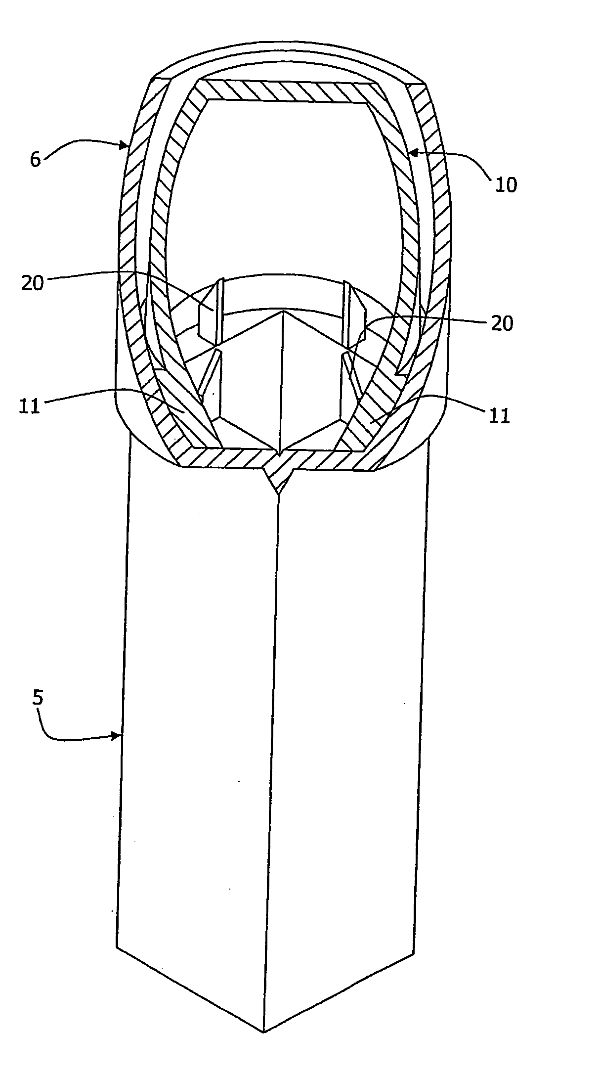
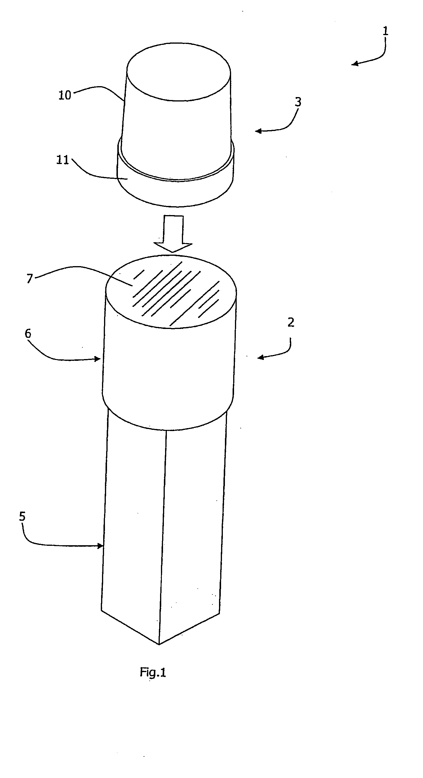
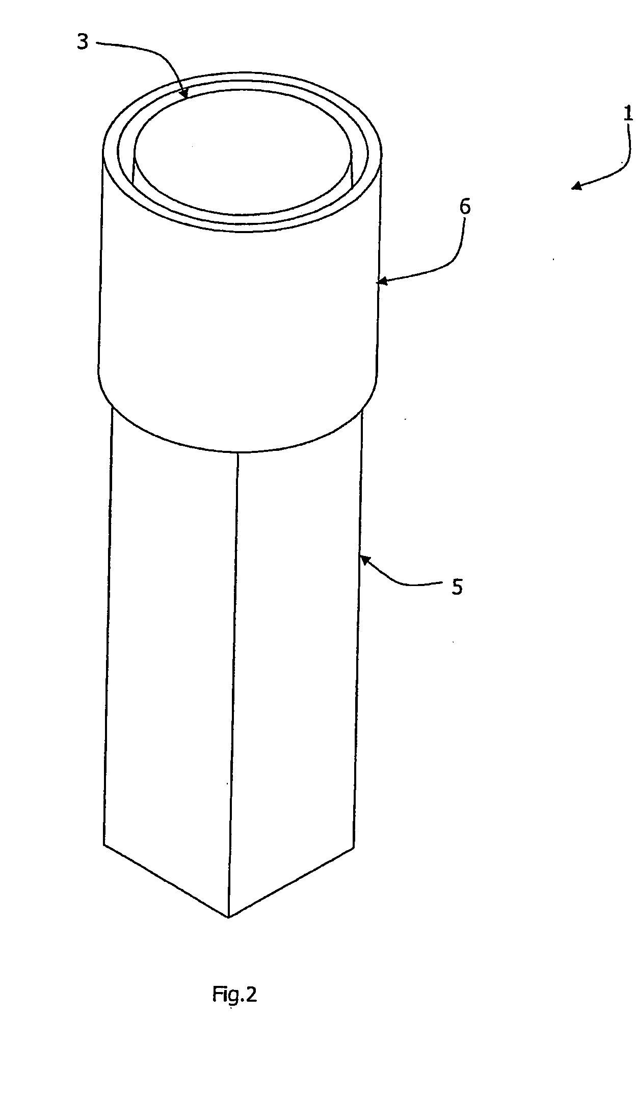
[0031] Referring to the drawings there is shown a reagent cuvette 1 for point-of-care analysis with laboratory accuracy. The cuvette 1 comprises two main parts, namely a first chamber 2 of approximately 64 mm height and a separate second chamber 3. The first chamber 2 and the second chamber 3 are of transparent plastics material. Both parts of the cuvette are of moulded plastics construction.

[0032] The first chamber 2 comprises an inspection part 5 and a socket 6 for receiving the chamber 3 in use, as described in more detail below. The inspection part 5 is of square cross-section, and extends for approximately two-thirds of the height of the chamber 2.

[0033] The socket 6 is of circular cross-section, tapering outwardly and upwardly at a small angle. It is wider than the inspection part 5, being connected to it by an integral shoulder. The chamber 2 is sealed by a foil membrane 7 extending across the top of the socket 6, and this seals in a buffer reagent supplied within the chamb...


PUM

PropertyMeasurementUnit
heightaaaaaaaaaa
frictionaaaaaaaaaa
thicknessaaaaaaaaaa

Abstract

A reagent cuvette (1) has a first chamber (2) with an inspection part (5) and a socket (6), and a second chamber (3). The socket (6) has four spikes (20) at its base. Both chambers are sealed with a membrane. At the point-of-care the foil membrane (7) of the first chamber (2) is peeled away by the therapist (typically general practitioner doctor). A sample, such as blood, is added to the chamber (2) using a pipette or other device to provide a verifiable quantity of sample. This provides a mixture of a buffer reagent supplied in the chamber (2) and the sample injected into the inspection chamber 2 at the point of care. The chamber (3) is then inserted into the socket (6) by gently pressing it down so that its foil membrane is broken by the spikes (20). This causes the starter reagent to drop down from within the second chamber (3) into the inspection part (5) of the first chamber (2). The inspection part (5) is then inserted into an optical inspection instrument for analysis of the two reagents and the sample mixed together.

Description

FIELD OF THE INVENTION [0001] The invention relates to a reagent cuvette for sample analysis. PRIOR ART DISCUSSION [0002] At present, there is often a two-stage analysis of samples, namely point-of-care and laboratory analysis. Typically, the point-of-care analysis is performed using “dry chemistry” techniques. This is because such techniques are simple and convenient to perform: a sample being placed on a strip coated with a dry reagent and the strip being inserted into an inspection instrument. [0003] The laboratory analysis is typically performed using “wet chemistry” techniques in which controlled volumes of fluid sample and reagent(s) are admixed and optically inspected. The “wet chemistry” techniques are regarded a being full and reliable tests, whereas the “dry chemistry” techniques are reliable only for screening purposes. Thus, a large number of patients may be unnecessarily subjected to the trouble and worry of further unwarranted tests beyond the point of care. [0004] The...

Claims


Application Information

Patent Timeline
Patent Type & Authority Applications(United States)
IPC IPC(8): B01L3/00B01L3/14G01N21/03
CPCB01L3/502B01L3/5082B01L3/50825B01L3/5635B01L2200/026B01L2200/16B01L2300/044B01L2300/047B01L2300/0672B01L2400/0683G01N21/03G01N2021/0321G01N2021/0325G01N2021/0364G01N2201/0245
Inventor O'DONOVAN, MICHAEL
Owner ODONOVAN MICHAEL
Why Eureka
Try Eureka