Torque limiter having two mechanical inlets

a technology of limiters and mechanical inlets, which is applied in the direction of valve details, rotorcrafts, couplings, etc., can solve the problems of increasing the torque exerted on the transmission system, running the risk of severely damaging the system, and another major difficulty to be taken into consideration

Active Publication Date: 2006-09-21
ARTUS +1
View PDF7 Cites 13 Cited by
  • Summary
  • Abstract
  • Description
  • Claims
  • Application Information

AI Technical Summary

Benefits of technology

[0024] Finally, the presence of pairs of self-blocking rollers, instead of a single wheel, is most advantageous insofar as it allows the torque limiter, and more particularly the first and second inlets, to operate in either direction of rotation, whether clockwise and anticlockwise.

Problems solved by technology

However, if some external element, e.g. an obstacle associated with the environment such as a wall or a gust of wind, should stop the blade moving while it is being folded, the torque exerted on the transmission system will increase, thereby running the risk of severely damaging the system.
However another major difficulty needs to be taken into consideration.
In the event of the motor of the automatic blade-folding device breaking down, it can become impossible to fold the blade, which can lead to major problems of shortage of space on board the ship where the helicopter is parked.
The folding device then becomes particularly complex, given the possibility of the motor jamming, which can impede maneuvering, and given the geometrical constraints imposed by the main rotor.

Method used


Image

  • Torque limiter having two mechanical inlets
  • Torque limiter having two mechanical inlets

Examples


Embodiment Construction

[0028] Elements shown in more than one figure are given the same reference in each figure.

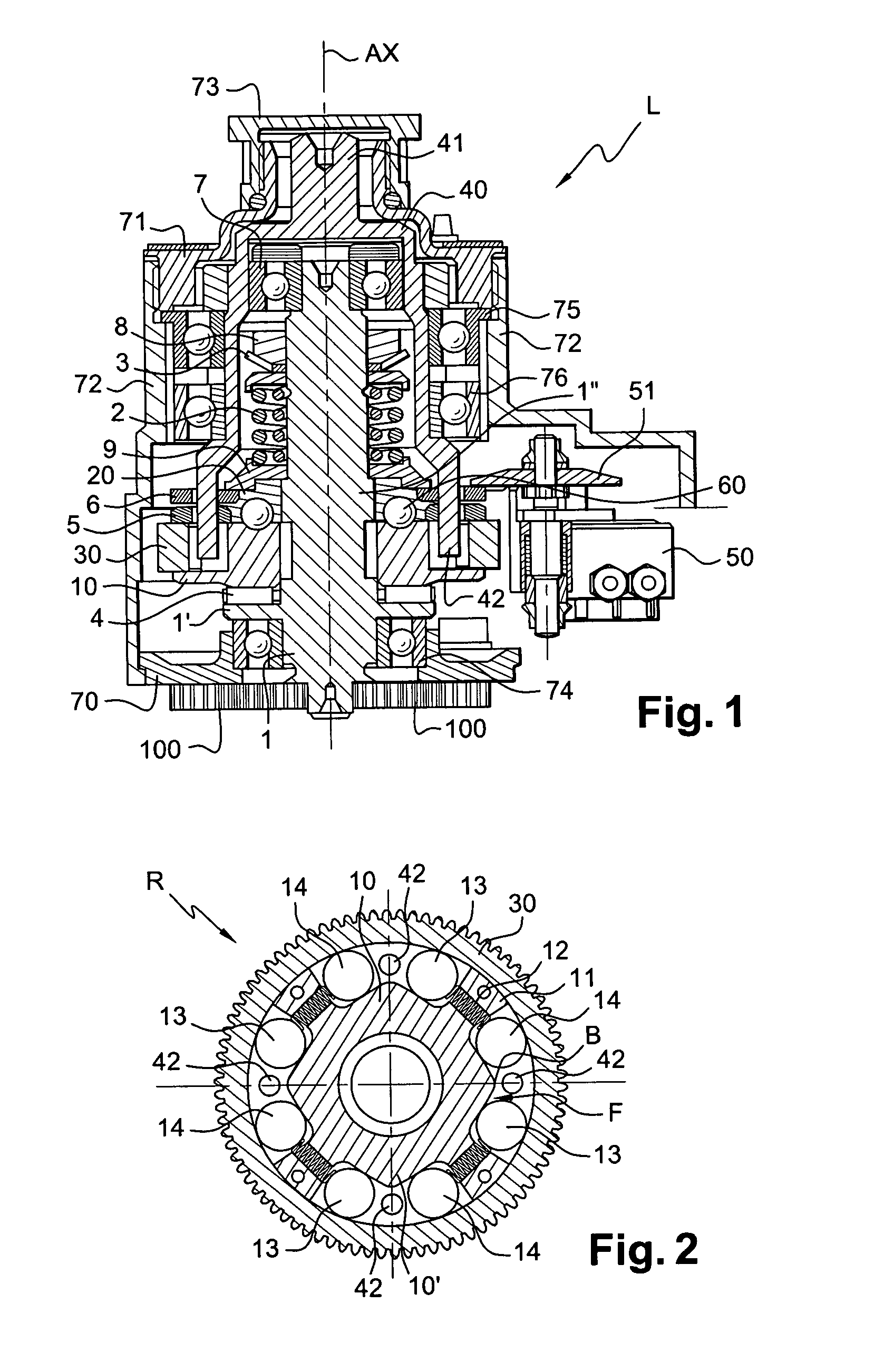
[0029]FIG. 1 is a section of a torque limiter L of the invention.

[0030] It comprises a bell 40 having a central shaft 1 inserted therein. In addition, a ball bearing 7, a nut 8, a washer 3 for braking the nut 8, a main spring 2, and a spacer 9 are disposed in succession between the bell 40 and the top portion of the central shaft 1 and are held axially between the first end 41 of the bell 40 and teeth 1″ on the central shaft 1.

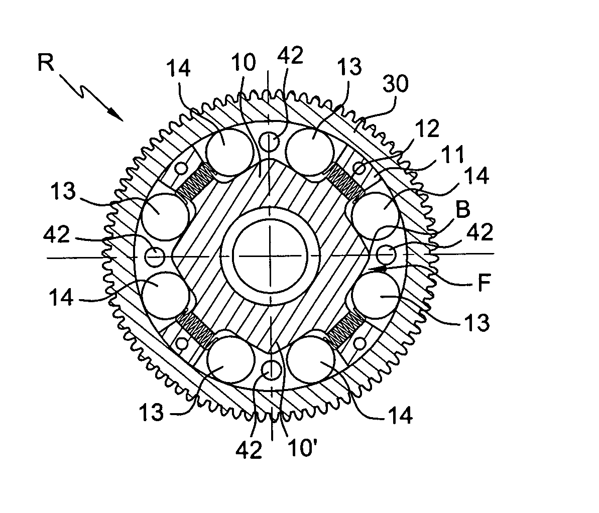
[0031] By means of these teeth 1″, the central shaft 1 can be rotated about its axis AX by a second plate 20. In turn, the second plate 20 is driven by a first plate 10 via a plurality of balls 60, each ball 60 being received in a housing constituted by first and second mutually-facing orifices formed respectively in the first and second plates 10 and 20. The first and second plates 10 and 20 possess the same axis of rotation AX and they are arranged radially between t...


PUM


Abstract

The present invention relates to torque limiter (L) provided with a first plate (10) that rotates a second plate (20) via a plurality of balls (60), said second plate (20) sharing the same axis as the first plate (10), each ball (60) being suitable for escaping from a respective housing in order to cease driving the second plate when the torque exceeds a predetermined threshold. Each housing comprises a first orifice and a second orifice facing each other and formed respectively in the first plate and in the second plate. The torque limiter (L) is remarkable in that it includes first and second distinct inlets for causing said first plate (10) to turn about its axis (AX).

Description

[0001] The present invention relates to a device having two mechanical inlets for limiting the torque exerted on a power transmission system so as to allow it to be operated both manually and automatically. [0002] The device is particularly well adapted to a system for automatically folding a blade of a main rotor for providing a helicopter with lift and forward drive, with a system of this type being particularly useful when the helicopter needs to be parked on board a ship. BACKGROUND OF THE INVENTION [0003] In order to fold a blade automatically, i.e. to cause it to pass from a flight configuration to a parking configuration, a motor drives a power transmission system for driving means for folding the blade. However, if some external element, e.g. an obstacle associated with the environment such as a wall or a gust of wind, should stop the blade moving while it is being folded, the torque exerted on the transmission system will increase, thereby running the risk of severely damag...

Claims


Application Information

Patent Timeline
Patent Type & Authority Applications(United States)
IPC IPC(8): F16D7/02
CPCB64C27/50F16D7/08F16D41/105F16D43/206
Inventor LOUIS, CHARLESQUESNE, PATRICK
Owner ARTUS
Why Eureka
Try Eureka