
Mattress sled

a mattress and sled technology, applied in the field of mattress sleds, can solve problems such as narrow mattress, and achieve the effect of low friction coating coefficien

Inactive Publication Date: 2006-09-28
DAVIS DAVID T
View PDF19 Cites 50 Cited by
  • Summary
  • Abstract
  • Description
  • Claims
  • Application Information

AI Technical Summary

Benefits of technology

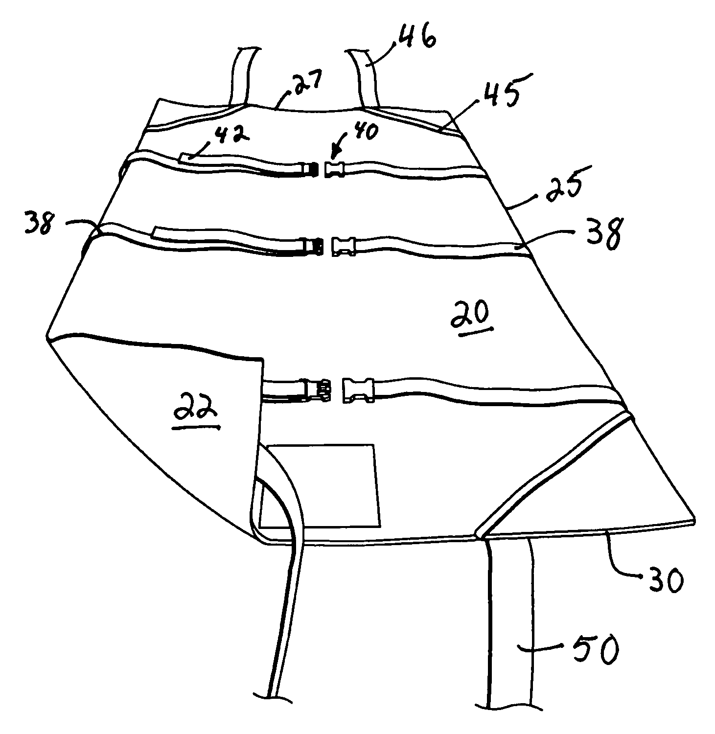
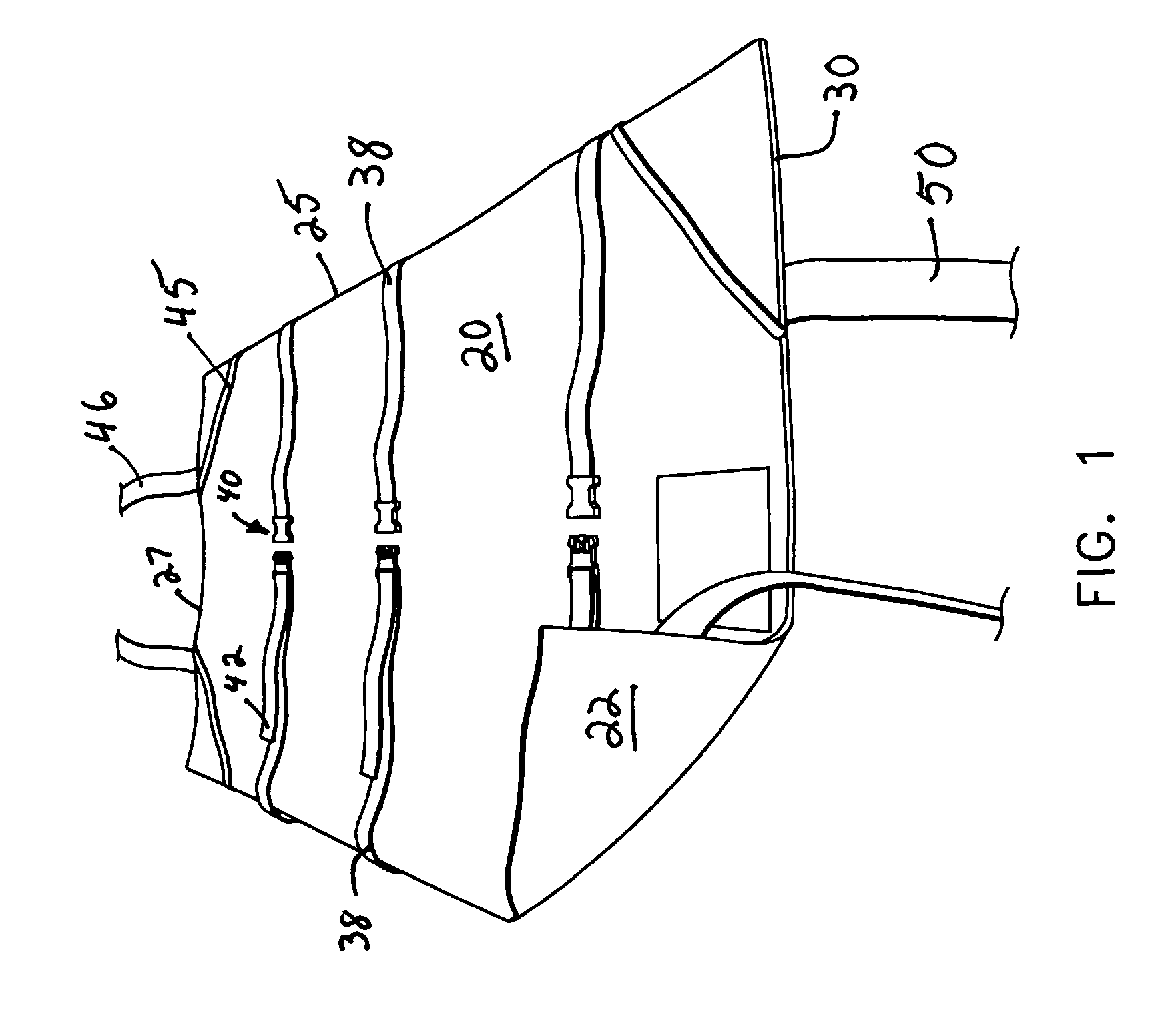
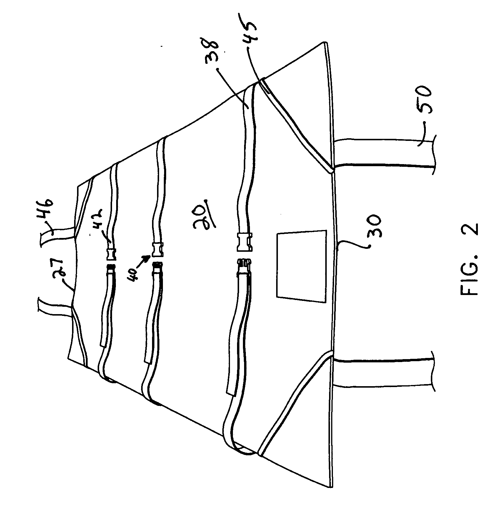
[0008] The present invention provides a system for transporting a nonambulatory patient. The patient is positioned upon a mattress having longitudinal sides and a bottom surface. A sled panel is located below the bottom surface of the mattress. The sled panel has longitudinal side edges, a head end edge, and a bottom surface that is covered with a low coefficient of friction coating. The sled panel also includes a plurality of side straps extending outwardly from each of its longitudinal side edges in spaced relation to one another. A handle is located at one or both ends of the sled panel. In an emergency, the side straps are wrapped around the mattress so as to cause the mattress to curl up upon itself so that the longitudinal sides are moved upwardly. This upward curling of the mattress' longitudinal side edges forms a central longitudinally oriented pocket that cradles or cocoons the patient. If the non-ambulatory patient needs to be moved in a hurry, e.g., during a fire emergency, an attendant may simply tighten the edge straps about the patient and mattress so as to curl the mattress around the patient. This action also tends to narrow the mattress. A handle is then grabbed so as to drag the curled mattress and cocooned patient from the bed upon the panel. The entire assembly is then dragged along a floor surface aided by the low coefficient of friction coating on the bottom surface of the sled panel.

Problems solved by technology

This action also tends to narrow the mattress.

Method used


Image

  • Mattress sled
  • Mattress sled
  • Mattress sled

Examples


Embodiment Construction

[0017] This description of preferred embodiments is intended to be read in connection with the accompanying drawings, which are to be considered part of the entire written description of this invention. The drawing figures are not necessarily to scale and certain features of the invention may be shown exaggerated in scale or in somewhat schematic form in the interest of clarity and conciseness. In the description, relative terms such as “horizontal,”“vertical,”“up,”“down,”“top” and “bottom” as well as derivatives thereof (e.g., “horizontally,”“downwardly,”“upwardly,” etc.) should be construed to refer to the orientation as then described or as shown in the drawing figure under discussion. These relative terms are for convenience of description and normally are not intended to require a particular orientation. Terms including “inwardly” versus “outwardly,”“longitudinal” versus “lateral” and the like are to be interpreted relative to one another or relative to an axis of elongation, o...


PUM


Abstract

A system for transporting an nonambulatory patient including a mattress having longitudinal sides and a bottom surface and a panel having longitudinal side edges, a head end edge, and a bottom surface coated with a low coefficient of friction coating. The panel is positioned below the bottom surface of the mattress, and includes a plurality of side straps extending outwardly from the longitudinal side edges in spaced relation to one another. A handle is located along at least one edge of the panel. The side straps are wrapped around the mattress so as to cause the mattress to curl so that the longitudinal sides are moved upwardly to thereby form a central longitudinal pocket suitable for cradling a patient positioned upon the mattress. The head end handle is then pulled to drag the curled mattress and the panel along a surface upon the low coefficient of friction coating.

Description

[0001] This application claims priority from co-pending Provisional Patent Application Ser. No. 60 / 664,313, filed Mar. 22, 2005, and entitled Safety Sled.FIELD OF THE INVENTION [0002] The present invention relates to patient evacuation devices for non-ambulatory or bed-ridden persons, and particularly to a device in which a patient may be rapidly and securely transferred while lying on a mattress. BACKGROUND OF THE INVENTION [0003] Many prior art methods and systems are known for shifting or moving a patient who is unable to move themselves. For example, in U.S. Pat. No. 4,793,008, a patient transfer mat is disclosed for aiding the moving of a patient who cannot move himself. The mat includes an elongated body portion with a substantially rectangular shape adapted to be placed transversely under the patient. The body portion is rigid yet flexible enough to at least partially conform to the contour of a portion of the patient's body. The mat includes grasping openings in each end wit...

Claims


Application Information

Patent Timeline
Patent Type & Authority Applications(United States)
IPC IPC(8): A61G7/14A61G1/00
CPCA61G7/0504A62B99/00
Inventor DAVIS, DAVID T.
Owner DAVIS DAVID T
Learn More