Reduced radar cross section exhaust nozzle assembly

a radar cross section and exhaust nozzle technology, applied in the direction of vessel construction, aircraft navigation control, marine propulsion, etc., can solve the problem of not being able to block or control all gaps created between adjacent flap assemblies, and achieve the effect of reducing and controlling the formation of gaps

Active Publication Date: 2006-09-28
RTX CORP
View PDF10 Cites 18 Cited by
  • Summary
  • Abstract
  • Description
  • Claims
  • Application Information

AI Technical Summary

Benefits of technology

[0006] This invention is an exhaust nozzle assembly including a plurality of interfitting flap assemblies having a wing portion and a slot portion. The wing portion of one flap fits within a slot portion of an adjacent flap to minimize and control formation of gaps between each of the flap assemblies.
[0007] The exhaust nozzle assembly includes a plurality of interfitting flap assemblies defining a variable cross-section opening. Pivoting of the flap assemblies about a fixed pivot varies the cross-sectional area of the opening. Each of the flap assemblies includes a divergent element, a flap element, and a seal. The seal is disposed between adjacent flap assemblies on an interior surface of the exhaust assembly to block gaps between adjacent flap assemblies. Each of the flap assemblies interfits into an adjacent flap assembly to provide a substantially uniform and continuous, faceted outer surface of the exhaust nozzle assembly.
[0008] Each of the seals includes a tented portion extending rearward from a trailing edge. The trailing edge of the seal includes a notch. The tented portion is disposed along a plane different than the substantial planar surface of the remaining portions of the seal. The tented portion is bent outwardly away from the interior surface of the flap assemblies. The notched and tented portions are disposed substantially at the trailing edge of the exhaust nozzle assembly to reduce and control formation of gaps between adjacent flap assemblies during articulation.
[0009] Accordingly, the exhaust nozzle assembly of this invention provides an improved flap assembly that reduces and controls gaps generated during articulation of a variable exhaust nozzle assembly.

Problems solved by technology

Disadvantageously, such seals cannot block or control all gaps created between adjacent flap assemblies during movement of the exhaust nozzle assembly.

Method used


Image

  • Reduced radar cross section exhaust nozzle assembly
  • Reduced radar cross section exhaust nozzle assembly
  • Reduced radar cross section exhaust nozzle assembly

Examples


Embodiment Construction

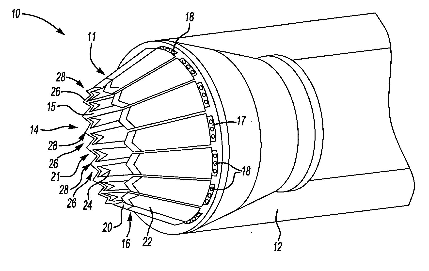
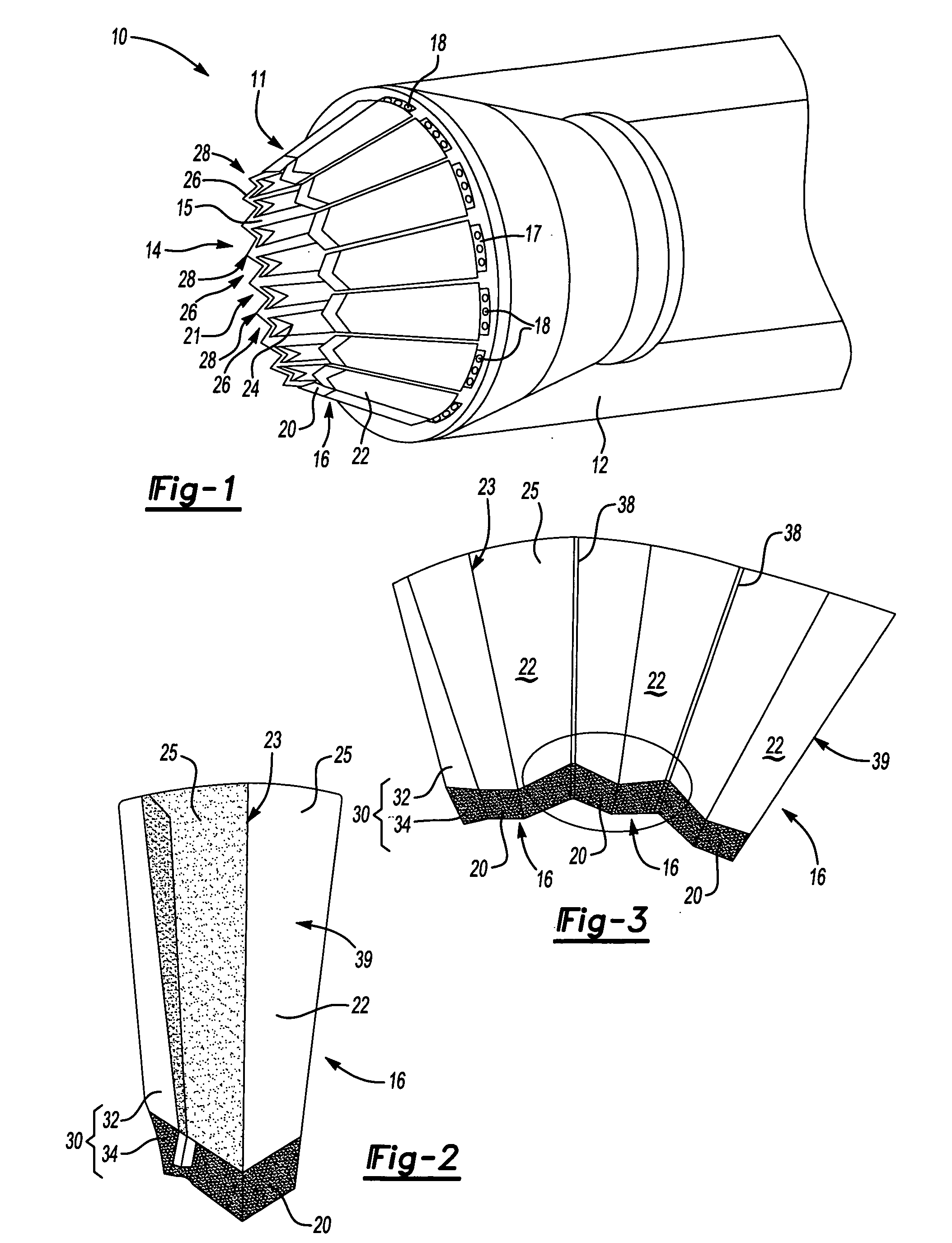
[0023] Referring to FIG. 1, an exhaust nozzle assembly 10 includes a plurality of interfitting flap assemblies 16 defining an opening 14. Each of the flap assemblies 16 is pivotally attached to a static structure at pivots 18. An actuator illustrated schematically at 17 is attached to move each of the flap assemblies 16. Pivoting of the flap assemblies 16 varies the cross-sectional area of the opening 14.

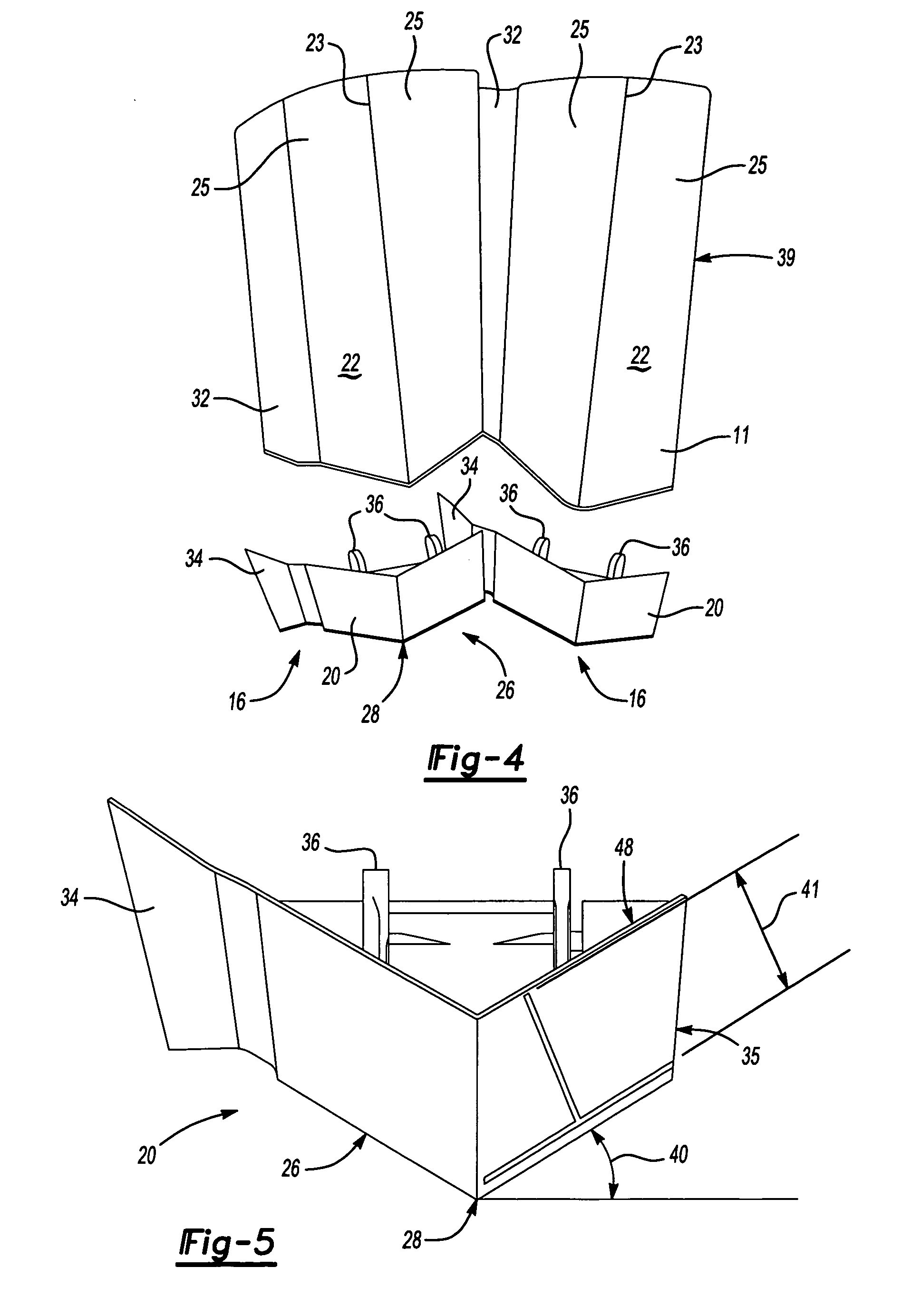
[0024] Each of the flap assemblies 16 includes a divergent element 20, a flap element 22, and a seal 24. The seal 24 is disposed between adjacent flap assemblies 16 on an interior surface 15 of the exhaust nozzle assembly 10 to substantially prevent leakage of exhaust gasses therethrough. Each of the flap assemblies 16 interfits into an adjacent flap assembly 16 to provide a substantially uniform and continuous, faceted outer surface 11 of the exhaust nozzle assembly 10. The opening 14 includes a serrated trailing edge 21 defined by the divergent elements 20 of each flap assembly 1...


PUM


Abstract

An exhaust nozzle assembly includes a plurality of interfitting flap assemblies that are moveable between a maximum area ratio and a minimum area ratio. Each of the pluralities of flap assemblies includes a slot and a wing. The wing fits within an adjacent slot of an adjacent flap assembly. Each of the flap assemblies includes a divergent element that provides a specific geometric shape forming the trailing edge surfaces. The flap element is attached to the divergent element and extends to a static structure. The flap element and the divergent element combine to form a continuous faceted outer surface of the exhaust nozzle assembly substantially void of gaps throughout the range of motion between the maximum and minimum area ratios.

Description

[0001] The US Government may have certain rights in this invention in accordance with Contract Number N00019-02-C-2003 awarded by the United States Navy.BACKGROUND OF THE INVENTION [0002] This invention relates generally to an exhaust nozzle assembly for a gas turbine engine. More particularly this invention relates to interfitting flap assemblies for a variable exhaust nozzle assembly. [0003] An exhaust nozzle for a gas turbine engine accelerates gas flow exiting the engine increasing thrust. A fixed exhaust nozzle including a fixed exhaust opening provides optimal performance for a single operating condition. A variable exhaust nozzle opens and closes to provide differing opening sizes to optimize performance for many operating conditions. Such exhaust nozzles typically include a plurality of flap sections moveable radially to change the opening area of the exhaust nozzle. [0004] Typically, a seal is provided on a hot side of the flaps for blocking a portion of a gap created betwe...

Claims


Application Information

Patent Timeline
Patent Type & Authority Applications(United States)
IPC IPC(8): F02K1/06
CPCF02K1/1207F02K1/805
Inventor ARBONA, JAIME A.HARRIS, MEGGANALLORE, JAMESLAPORTE, STEVEN
Owner RTX CORP
Why Eureka
Try Eureka