
Downhole recovery production tube system

a production tube and recovery technology, applied in the field of oil well production tube system, can solve the problems of unavoidable improvement, rigidity, and prone to leaking recovered fluid from segmented production tubes, and achieve the effect of safe extension of electrical power lines, simple tack-welding, and elimination of unstabilizing movement of power tubes

Inactive Publication Date: 2006-09-28
CRAWFORD JOE
View PDF42 Cites 7 Cited by
  • Summary
  • Abstract
  • Description
  • Claims
  • Application Information

AI Technical Summary

Benefits of technology

The present invention is an improved downhole recovery production tube system that solves problems associated with current systems. It uses coilable power tubes placed inside a larger coiled production tube, which eliminates the need for separate hydraulic lines and pumps. The system also includes a fabrication process that allows for the continuous coilable tube to be formed by joining consecutive lengths of stock metal at supplemental angles, welded together, and then shaped into tubular form with a seam running along its length. The smaller power tubes must be properly spaced to ensure they remain aligned with one another, and this alignment is important for stability during operation. The invention offers several advantages over current systems, including faster installation times and reduced costs.

Problems solved by technology

While these devices may fulfill their respective, particularly claimed objectives and requirements, the aforementioned devices do not disclose an improved oil well production tube system such as Applicant's present invention.
Several problems are unavoidable with systems employing this type of production tubing.
For example, a rigid, segmented production tube is prone to leaking recovered fluid about the point where individual segments are joined together.
These problems are exaggerated when a well bore becomes warped or deviated; as such, many times rigid segments cannot be used in multiple well bores.
Further, individual production tube segments are subject to cross-threading or other thread damage that may compromise the mechanical integrity of the production tube.
However, these types of systems present several problems.
Even when this protection is utilized, cable damage can occur that causes an electrical short in the cable when power is applied.
It is not uncommon for the bands that hold electrical cable to break or be installed improperly.
When this occurs, since the armored electrical cable is not capable of supporting its own weight for the entire length of the production assembly, other straps break, ultimately resulting in a cable failure.
In such an event, cable recovery from the well bore is an expensive and often unsuccessful process.
Additionally, occasionally the production tube disjoins and subsequently severs the electrical cable; of course, such a combination is especially difficult to retrieve from the well bore.
Other practical difficulties are associated with the use of electrical cables in artificial lift recovery systems.
Specifically, as a result of gaps between the electrical cable and production tube, and the electrical cable and protective armor, current blowout preventers can not achieve a 100% positive seal.
Also, the well bore inside diameter must be large enough to house both the production tube and the electrical cable, which of course, limits the installing of large capacity pumps in smaller diameter well bores.
Nevertheless, seemingly unavoidable problems are a major concern for those skilled in the art.
Use of a single coilable production tube provides no means for efficient hydraulic power communication between the surface and a downhole recovery device.
Specifically, the use of coliable production tube, alone, does not provide for efficient or reliable power communication between the surface and a downhole recovery device.
Known coilable production tube manufacturing processes do not lend themselves to placing smaller coilable, power tubes within a larger coilable production tube.
Specifically, no fabrication process has been developed to allow for such a configuration.
However, this procedure is far from practical as binding, kinking, and sliding friction make for an all to difficult task.

Method used


Image

  • Downhole recovery production tube system
  • Downhole recovery production tube system
  • Downhole recovery production tube system

Examples


Embodiment Construction

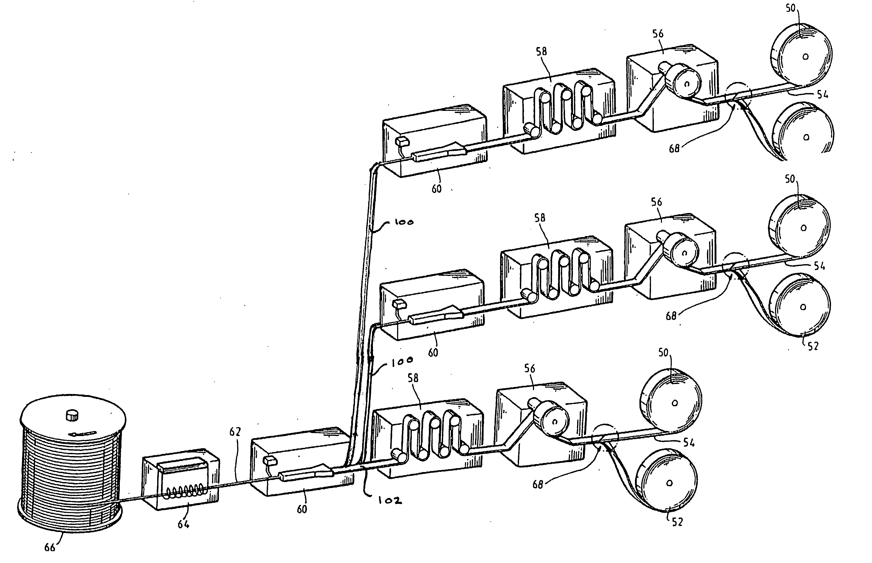
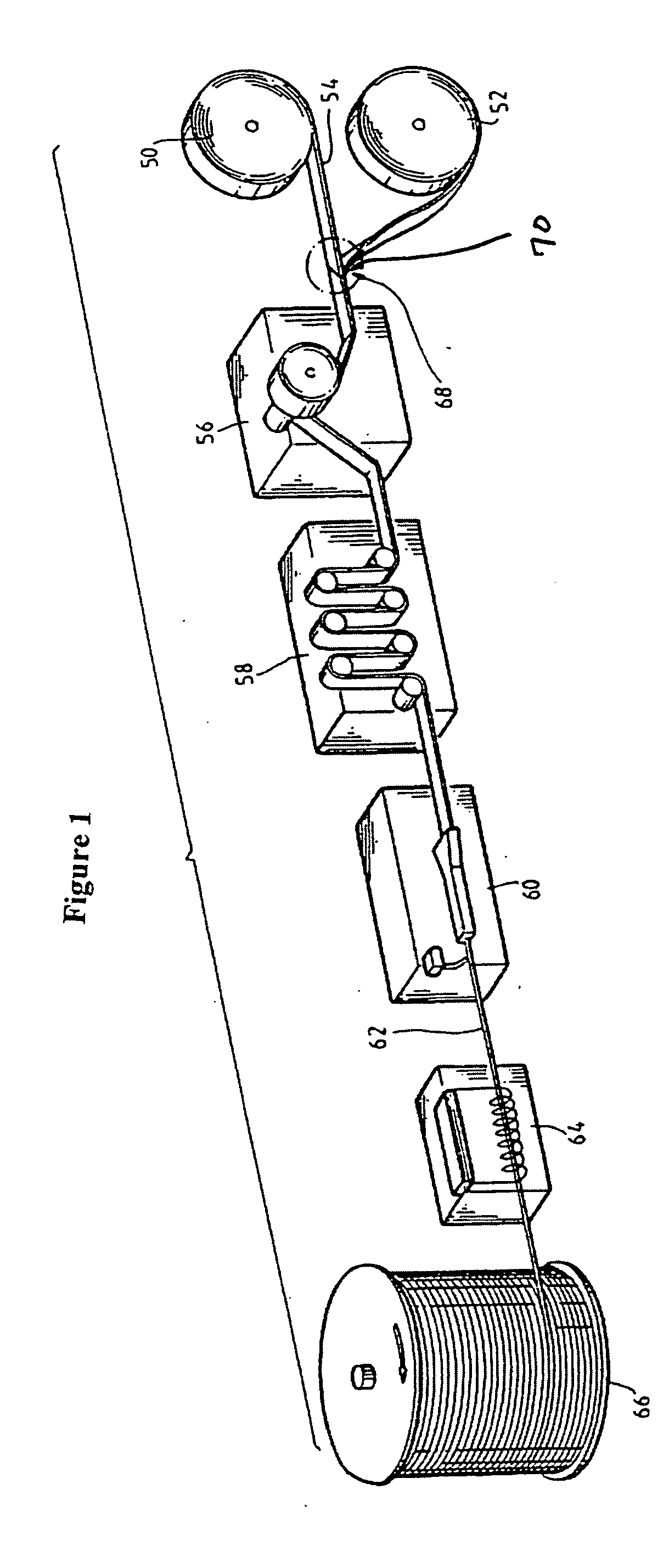
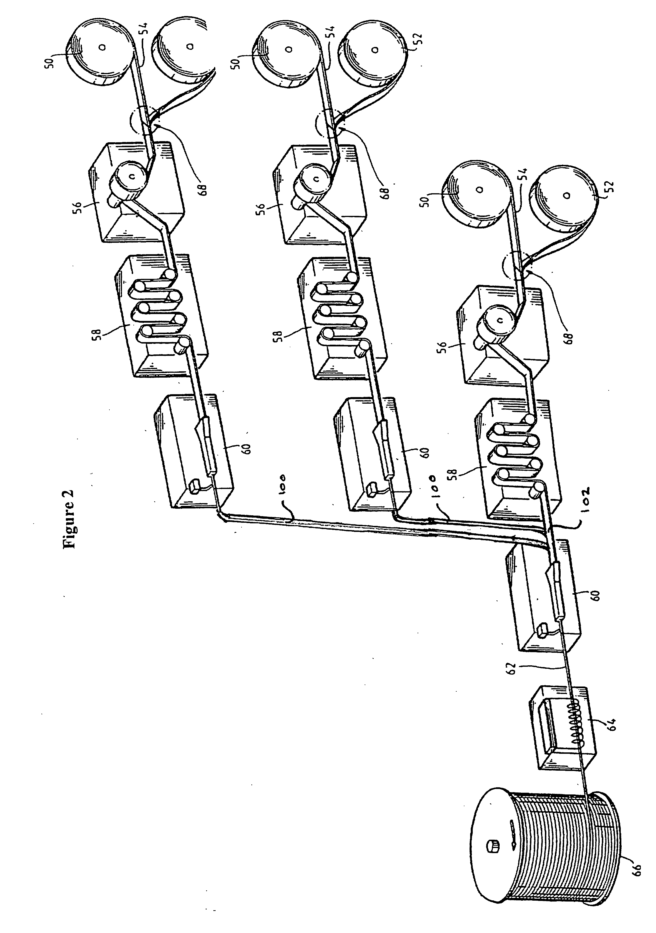
[0033] Referring to FIG. 1, a prior art system of producing a tubing string from flat sheet metal strips is shown. Such is disclosed in U.S. Pat. No. 4,863,091 and U.S. Pat. No. 5,191,911, each of which is hereby expressly incorporated by reference. In this system, the apparatus includes master coils 50 and 52, an accumulator 56, a feed stock conditioner 58, a tube former 60, a heat treater 64, and a reel 66. As known in the art, stock metal is deployed from master coils 50 and 52 and is “run through” accumulator 56. Differential action on the part of accumulator 56 allows a second length of strip stock to be spliced onto the trailing end of a preceding length while the latter is still housed in accumulator 56. Splice 68 is formed by cutting strip ends to be spliced at supplementary angles, including an acute angle of about thirty degrees. A small piece 70 is attached to each end of splice joint 68 to act as a heat sink and provide for improved weld strength. A welding tool is passe...


PUM

PropertyMeasurementUnit
lengthaaaaaaaaaa
lengthaaaaaaaaaa
acute angleaaaaaaaaaa

Abstract

An improved oil well production tube system characterized by a series of seam-welded, coilable tubes configured for placement in a subterranean fluid recovery well. Smaller coilable tubes, contained within a larger coilable tube, are configured for providing power communication between the surface and a downhole recovery means. The larger coilable tube is configured for providing communication of a recovered fluid from downhole to the surface. During fabrication, one or more smaller coilable tubes is introduced along the surface of a length of flat strip metal. The smaller coilable tubes are preferably tack-welded to the surface of the flat strip metal at determined intervals along their length. The length of flat strip metal is formed into tubular form and seam welded to form a coilable tube containing the smaller tubes therein.

Description

CITATION TO PRIOR APPLICATION [0001] This application claims the benefit of U.S. Provisional Application No. 60 / 651,873, filed on Feb. 8, 2005.BACKGROUND OF THE INVENTION [0002] 1. Field of the Invention [0003] The present invention generally relates to an improved oil well production tube system. More specifically, the present invention relates to an oil well production tube system where one or more smaller coilable power tubes is placed within a larger coilable production tube. [0004] 2. Background Information [0005] The use of coilable production tubing for the transfer of fluid from a subterranean source to the surface is known in the art. However, such production tubing systems heretofore devised and utilized are known to consist basically of familiar, expected and obvious structural configurations, notwithstanding the several designs encompassed by the prior art which have been developed for the fulfillment of many objectives and requirements. While these devices may fulfill t...

Claims


Application Information

Patent Timeline
Patent Type & Authority Applications(United States)
IPC IPC(8): F16L9/18B21C37/06F16L11/00
CPCB21C37/08B21C37/151Y10T29/49924F16L9/19E21B17/203
Inventor CRAWFORD, JOE
Owner CRAWFORD JOE
Learn More