Rotational set well packer device

a packer device and rotating technology, applied in the direction of sealing/packing, fluid removal, borehole/well accessories, etc., can solve the problems of inability to retrieve production tubing along with the tool string without resorting to costly fishing expedients, and the difficulty of unscrewing the components of the packer that unseat or relax the packer elements

Inactive Publication Date: 2006-09-28
CLIFTON HAROLD DEAN
View PDF19 Cites 16 Cited by
  • Summary
  • Abstract
  • Description
  • Claims
  • Application Information

AI Technical Summary

Benefits of technology

[0011] Oil field tools, especially packer devices or packer apparatus, are fabricated with right hand or clockwise rotation for setting the resilient packer elements thereof, whereupon fluid flow thereacross is precluded. One primary function of a packer device as described herein is to arrange the packer elements in series respective the tubing string whereby the annulus formed between the production tubing and the well casing prevents uphole flow of well fluid when the packer elements are expanded and set into engagement with the wall of the casing, thereby filling the annulus between the tubing and casing, whereupon both uphole and downhole flow of well fluid is prevented.
[0017] Those skilled in the art, after digesting this entire disclosure, will appreciate that this disclosed packer device can be run above a tubing anchor along with other tools, such as a gas separator hookup, for example. This invention includes equalizing or drain ports that facilitate running and pulling the packer. In the present packer apparatus, approximately three turns left are required to set the packer elements, and right hand rotation to release the packer elements. The tubing can be placed in tension, compression or neutral. Low torque is required for setting the packer elements, and there are no slips or moving parts to wear out from pump movement. When desired, two packers can be run in the same string to isolate a zone for pumping, and furthermore, this packer can be run below a casing leak or perforations, and preferably is fabricated of stainless steel to further avoid the likelihood of corroded threads.

Problems solved by technology

Packer apparatus often remain downhole for extended lengths of time and when the time arrives to remove the tool string for one reason or another, the deleterious affects of the well fluids may have corroded the various coacting parts of the packer apparatus, making it difficult to unscrew the components of the packer that unseat or relax the packer elements.
Consequently, when downhole problems arise, the packer and the tubing anchor must be unseated, or released from engagement with the casing, otherwise the production tubing along with the tool string cannot be retrieved without resorting to costly fishing expedients.

Method used


Image

  • Rotational set well packer device
  • Rotational set well packer device
  • Rotational set well packer device

Examples


Embodiment Construction

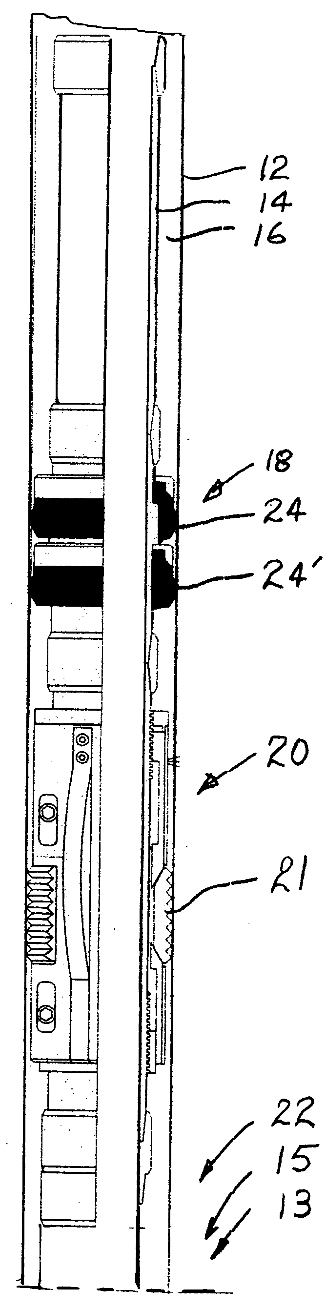
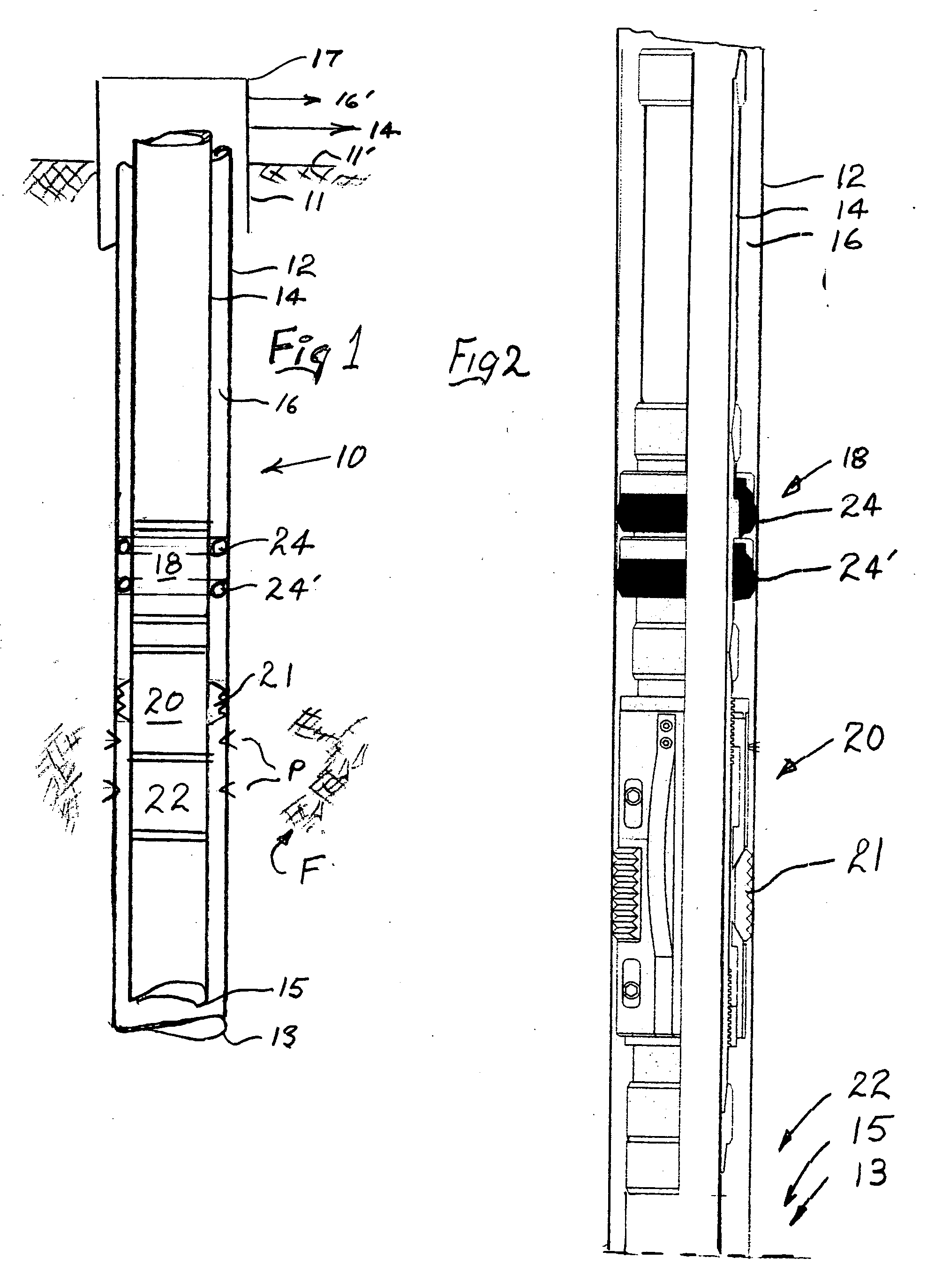
[0031]FIG. 1 of the drawings diagrammatically discloses a producing well bore 10 formed through the surface of the earth and extends downhole through a fluid producing formation F. There is a surface pipe or upper casing 11 for protecting the upper aquifer. Within surface casing 11 there is axially received a main well casing 12 extending downhole into proximity of the bottom 13 of the borehole. Production tubing 14 is also axially received respective casings 11 and 12. Accordingly, an annulus 16 is formed between casing 12 and tubing 14. Tubing 14 is a production pipe string, sometime referred to as a tool string for it is series connected respective to various oil field apparatus such as, for example only, the instant packer device 18, made in accordance with this invention, the details of which are more fully described later on herein.

[0032] The surface casing 11, well casing 12, and production tubing 14 are attached to a wellhead 17, also called a Christmas tree.

[0033] The tub...


PUM


Abstract

A packer apparatus that is set with low friction counter-clockwise rotation, and unset with clockwise rotation. A drain valve is opened concurrently as the packer apparatus is unset and closed as the packer apparatus is set. The Packer apparatus requires a minimum of parts and is designed to be used in corrosive environments.

Description

CROSS-REFERENCE TO RELATED APPLICATIONS [0001] Provisional Patent Application [0002] Ser. No. 60 / 664,844 Filed Mar. 23, 2005 [0003] Entitled “ROTATIONAL SET WELL PACKER DEVICE”[0004] Inventor: Harold Dean Clifton [0005] Midland , Tex. 79707STATEMENT REGARDING FEDERALLY SPONSORED RESEARCH OR DEVELOPMENT [0006] Not Applicable. REFERENCE TO A MICROFICHE APPENDIX [0007] Not Applicable BACKGROUND [0008] This patent application discloses to those skilled in the art a rotational set packer device for use in oil and gas exploration and production. [0009] The packer device of this invention is of the type that is insertable from the top of a well, which usually will be into a well casing, or other conduit. The packer device broadly comprises means, usually known in the oil field as a packer device or packer apparatus having expansible, resilient packer elements. The packer device is considered a downhole tool forming a part of a tool string for use in isolating various parts of a wellbore or...

Claims


Application Information

Patent Timeline
Patent Type & Authority Applications(United States)
IPC IPC(8): E21B23/02
CPCE21B23/06E21B33/128
Inventor CLIFTON, HAROLD DEAN
Owner CLIFTON HAROLD DEAN
Why Eureka
Try Eureka