Automated deployable running board

Active Publication Date: 2006-09-28
MAGNA INTERNATIONAL INC
View PDF11 Cites 73 Cited by
  • Summary
  • Abstract
  • Description
  • Claims
  • Application Information

AI Technical Summary

Benefits of technology

[0006] It is an object of the present invention to provide new and improved automat

Problems solved by technology

A problem associated with conventional automated running board systems is to design an extremely low-profile running board system that would provide a sufficient board length and width that deploys and retracts to a mid point between ground level and the top of door sill.
For example, with very limited packaging space available under the side of vehicle (i.e., w

Method used


Image

  • Automated deployable running board
  • Automated deployable running board
  • Automated deployable running board

Examples


first embodiment

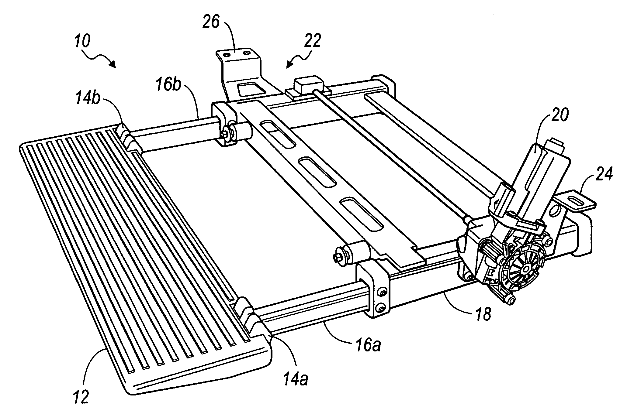
[0033] Referring to FIG. 1, there is shown a perspective view of running board system 10 (in this view, in the deployed position), in accordance with the present invention.

[0034] The system 10 primarily includes a running board member 12, a pair of pivot assemblies 14a, 14b, respectively, operably associated with a side edge portion of the running board member 10 to impart rotational (e.g., vertical) movement thereto, a pair of arm assemblies 16a, 16b, respectively, operably associated with a portion of the pivot assemblies 14a, 14b, respectively, an optional housing 18 (either sealed or unsealed) operable to receive at least a portion of the arm assemblies 16a, 16b, respectively, and a motorized drive assembly 20 operable to impart linear (e.g., horizontal) movement to the arm assemblies 16a, 16b, respectively. An optional mounting system 22 is shown including mounting bracket members 24, 26, respectively, for mounting the system 10 to a surface of a vehicle. A slave drive assembly...

second embodiment

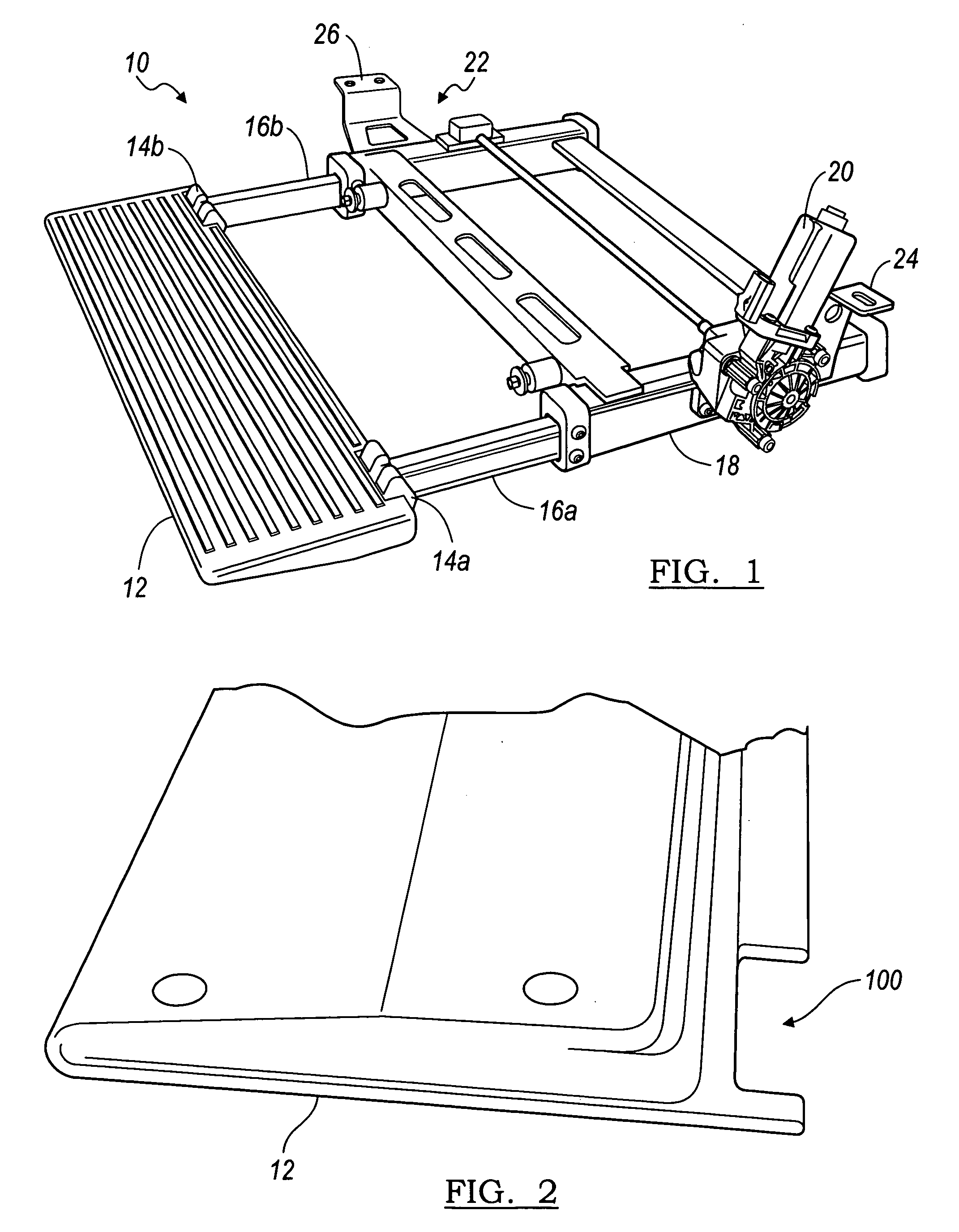
[0035] Referring to FIG. 2, there is shown a perspective view of the running board member 12 depicted in FIG. 1, in accordance with the present invention. The running board member 12 is shown as being substantially wedge-shaped, although it is envisioned that other configurations can be employed in the practice of the present invention. The running board member 12 is preferably provided with at least one area defining a notch 100, e.g., to receive a portion of the pivot assembly 14. It should be appreciated that a notch would be formed on two spaced portions of one side edge portion of the running board member 12 to receive a portion of the pivot assemblies 14a, 14b, respectively.

third embodiment

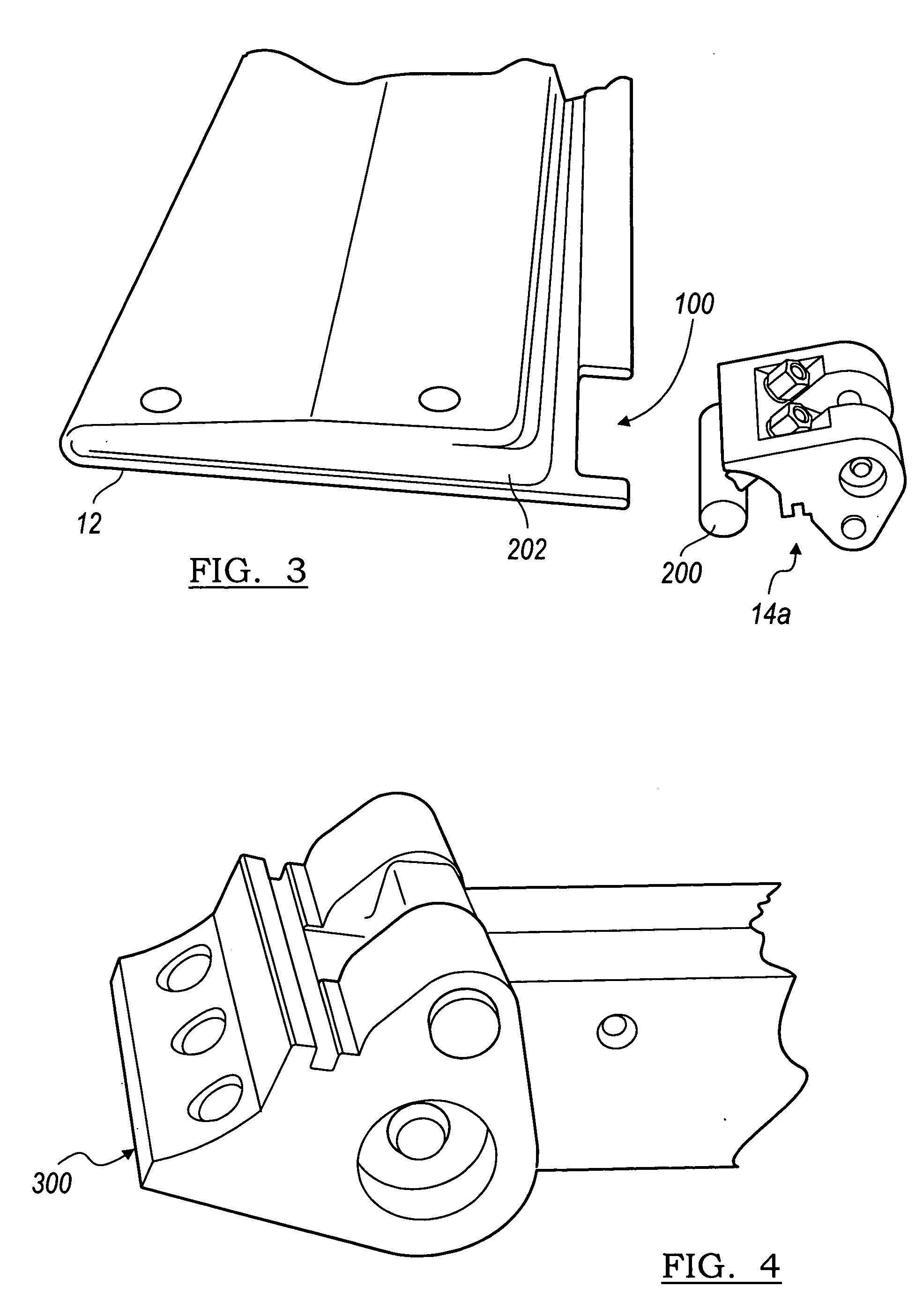
[0036] Referring to FIG. 3, there is shown an exploded view of the running board member 10 and one of the pivot assemblies 14a depicted in FIG. 1, in accordance with the present invention. The pivot assembly 14a (as well as pivot assembly 14b) includes a tongue portion 200 that is operable to be received in a groove 202 formed in the running board member 12. A portion of the pivot assembly 14a is then received in the notch 100. In this manner, the running board member 12 is substantially rigidly fastened to the pivot assemblies 14a, 14b, respectively.


PUM


Abstract

Running board systems are provided. The running board systems employ a motorized drive system that includes a rack-and-pinion system that enables both linear and rotational movement of the running board member, for example, through the use of a pivot member cooperating with one end of the running board member and one end of an arm member. The running board systems are automated and selectively operable to assume deployed and stowed positions. The running board systems can be used in conjunction with various surfaces of a vehicle, such as an aesthetically preferred flush style mounting to the rocker outer sheet metal surface such as but not limited to being mounted underneath a side door sill.

Description

CROSS-REFERENCE TO RELATED APPLICATION [0001] The instant application claims priority to U.S. Provisional Patent Application Ser. No. 60 / 665,114, filed Mar. 25, 2005, the entire specification of which is expressly incorporated herein by reference.FIELD OF THE INVENTION [0002] The present invention relates generally to running board systems, and more specifically to automated running board systems that are selectively deployable and stowable, wherein the systems have a substantially small overall section height and can be deployed at a desired height and position relative to the vehicle and components thereof. BACKGROUND OF THE INVENTION [0003] A running board is typically a small ledge, step, or footboard, located beneath the doors of an automobile, to assist passengers entering or leaving the car. Running boards are typically employed on larger vehicles, such as minivans, sport utility vehicles, trucks, and / or the like, where passengers may need assistance entering and exiting the ...

Claims


Application Information

Patent Timeline
IPC IPC(8): B60R3/00
CPCB60R3/02
Inventor WATSON, BRAD
Owner MAGNA INTERNATIONAL INC
Why Eureka
Try Eureka