Energy converter utilizing electrostatics

a technology of electrostatics and energy converters, applied in the direction of generators/motors, device details, device details, etc., can solve the problems of limiting the compactness of electromagnetic motors and generators, reducing reliability, and limiting energy efficiency

Inactive Publication Date: 2006-09-28
SALMON PETER C
View PDF21 Cites 39 Cited by
  • Summary
  • Abstract
  • Description
  • Claims
  • Application Information

AI Technical Summary

Problems solved by technology

The coils are formed in three dimensions and this limits the compactness of electromagnetic motors and generators.
Additionally, the motive force is proportional to the current in the coils, and

Method used


Image

  • Energy converter utilizing electrostatics
  • Energy converter utilizing electrostatics
  • Energy converter utilizing electrostatics

Examples


Embodiment Construction

[0035] Various embodiments of the present invention are described hereinafter with reference to the figures. It should also be noted that the figures are only intended to facilitate the description of specific embodiments of the invention. They are not intended as an exhaustive description of the invention or as a limitation on the scope of the invention. In addition, an aspect described in conjunction with a particular embodiment of the present invention is not necessarily limited to that embodiment and can be practiced in any other embodiments.

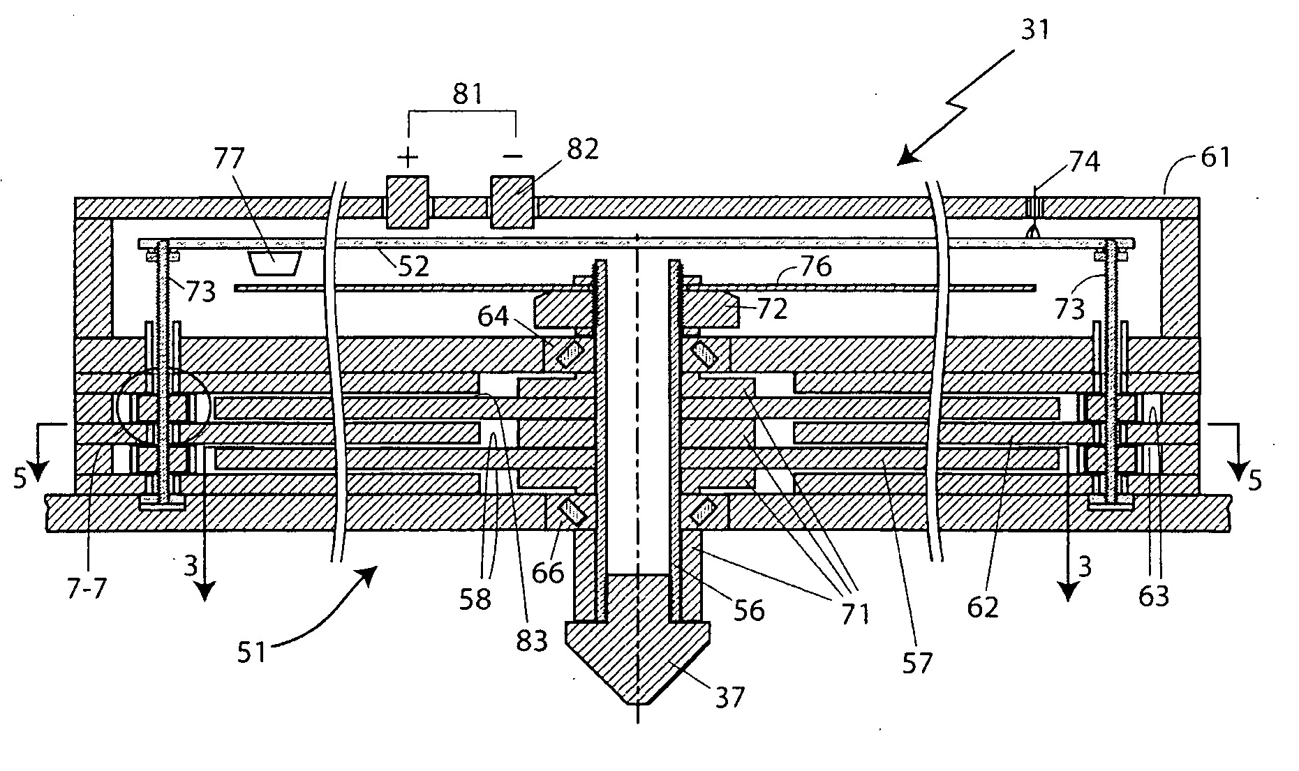
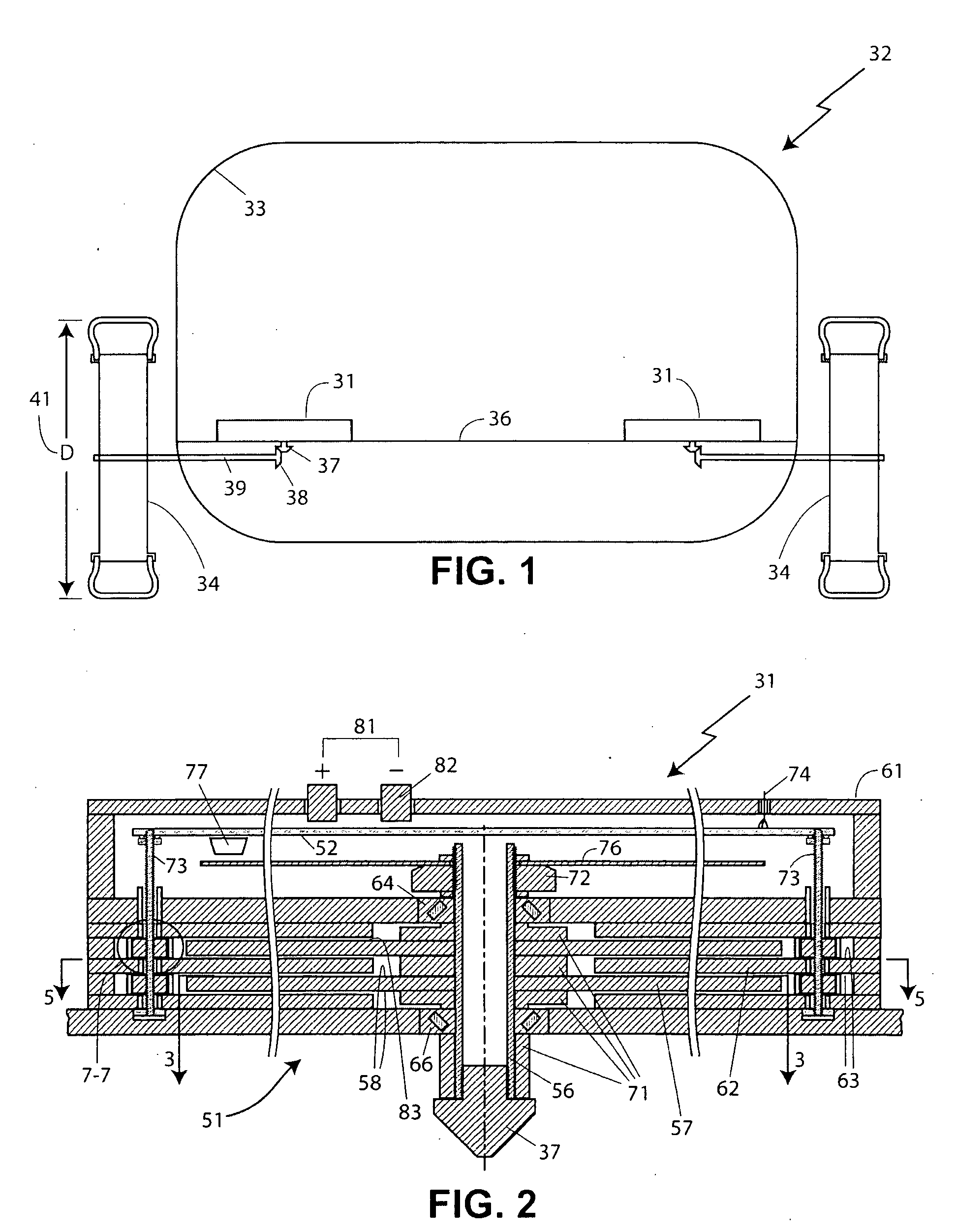
[0036] For instance, energy converters are described including both an energy conversion portion and a controller portion. It will be appreciated that these can be packaged and used separately. Although the preferred embodiments include application for transportation vehicles, industrial motor / generators, and hand-held compact motors, other embodiments and applications will be apparent to those who are skilled in the art.

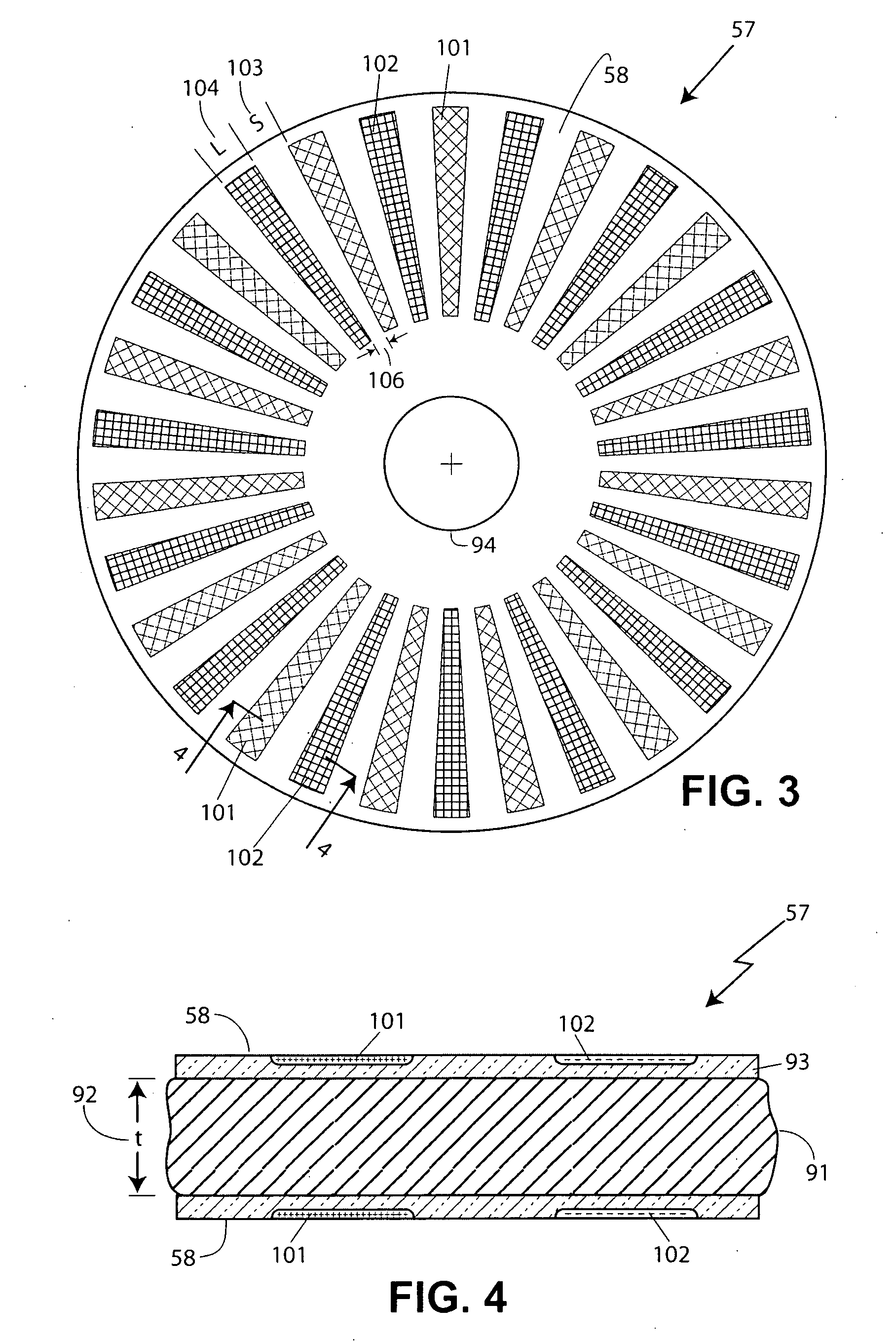
[0037] An energy c...


PUM


Abstract

An electrostatic energy converter comprising a rotor having a working surface provided with a plurality of distinct charged regions. A stator extends parallel to the rotor and has a working surface facing the working surface of the rotor and being provided with a plurality of spaced-apart electrodes. A power supply is coupled to the electrodes.

Description

CROSS REFERENCE TO RELATED APPLICATIONS [0001] This application claims priority to Provisional Application Ser. No. 60 / 664,321 filed Mar. 22, 2005, the entire content of which is incorporated herein by reference this reference.FIELD OF THE INVENTION [0002] This invention relates to energy converters and more particularly to electrostatic motors and generators. DESCRIPTION OF THE RELATED ART [0003] Energy converters such as electric motors employing electromagnetic forces have been the dominant motor type for many decades. Generally they comprise a moving element and a stationary element, at least one of which includes coils through which current is passing to create a magnetic field. This magnetic field acts on a permanent magnet or on a coil carrying current provided on the other member to create a motive force by which relative motion between the elements is produced. The coils are formed in three dimensions and this limits the compactness of electromagnetic motors and generators....

Claims


Application Information

Patent Timeline
IPC IPC(8): H02N1/00H01L41/04
CPCH02N1/004B60K7/0007B60K2007/0046B60K2007/0084
Inventor SALMON, PETER C.
Owner SALMON PETER C
Why Eureka
Try Eureka