Systems and Methods For the Treatment of Eye Conditions

a system and eye condition technology, applied in the field of medical devices, can solve the problems of evaporative dry eye disease, thickened meibum that cannot be easily withdrawn from the glands, and easy evaporation, and achieve the effect of minimizing the amount of energy

Active Publication Date: 2015-01-01
ALCON INC
View PDF5 Cites 55 Cited by
  • Summary
  • Abstract
  • Description
  • Claims
  • Application Information

AI Technical Summary

Benefits of technology

[0031]In some embodiments, the waveguide includes a shaped reflective surface. The energy transducer and the waveguide may be configured to direct the energy at the...

Problems solved by technology

When sufficient meibum is not present in the tear film, the film readily evaporates, leading to evaporative dry eye disease.
In some patients, the viscosity and melting point of the meibum may elevate, resulting in thickened meibum that does not flow easily out of the glands.
Further, the channel or duct within the meibomian gland may become hyperkeratinized, leading to excessive cellular debris and contributing to the clogging of the gland over time.
Once the glands become chronically clogged (inspissated), they may atrophy, and no longer be able to produce or secrete meibum.
By-products of the bacteria are thought to be irritating to the eye, leading to further inflammation and discomfort to the patient.
The inflammation caused by these factors can lead to further constriction of the meibomian gland ducts, limiting the flow of meibum from the glands and aggravating the condition.
The disadvantage of these transillumination techniques is that they require the lid to be everted, which is uncomfortable for most patients, and which can be difficult for the clinician to perform on some eyelids.
MGD and blepharitis are chronic conditions with limited effective treatment.
However, the efficacy of such an approach may be limited.
In-office treatment of MGD is often limited to squeezing the affected eyelids in order to express meibum...

Method used


Image

  • Systems and Methods For the Treatment of Eye Conditions
  • Systems and Methods For the Treatment of Eye Conditions
  • Systems and Methods For the Treatment of Eye Conditions

Examples


Embodiment Construction

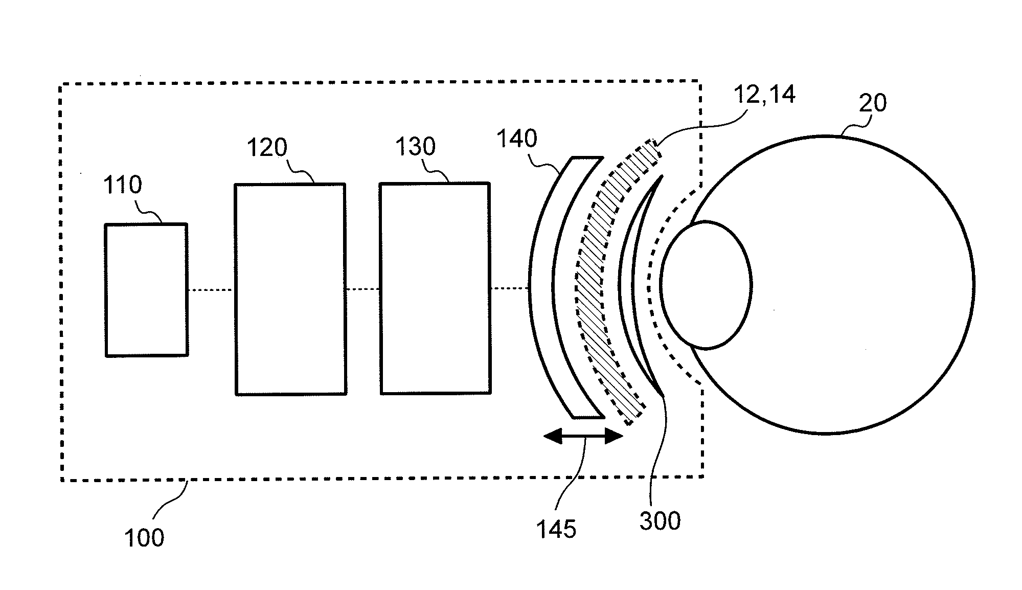
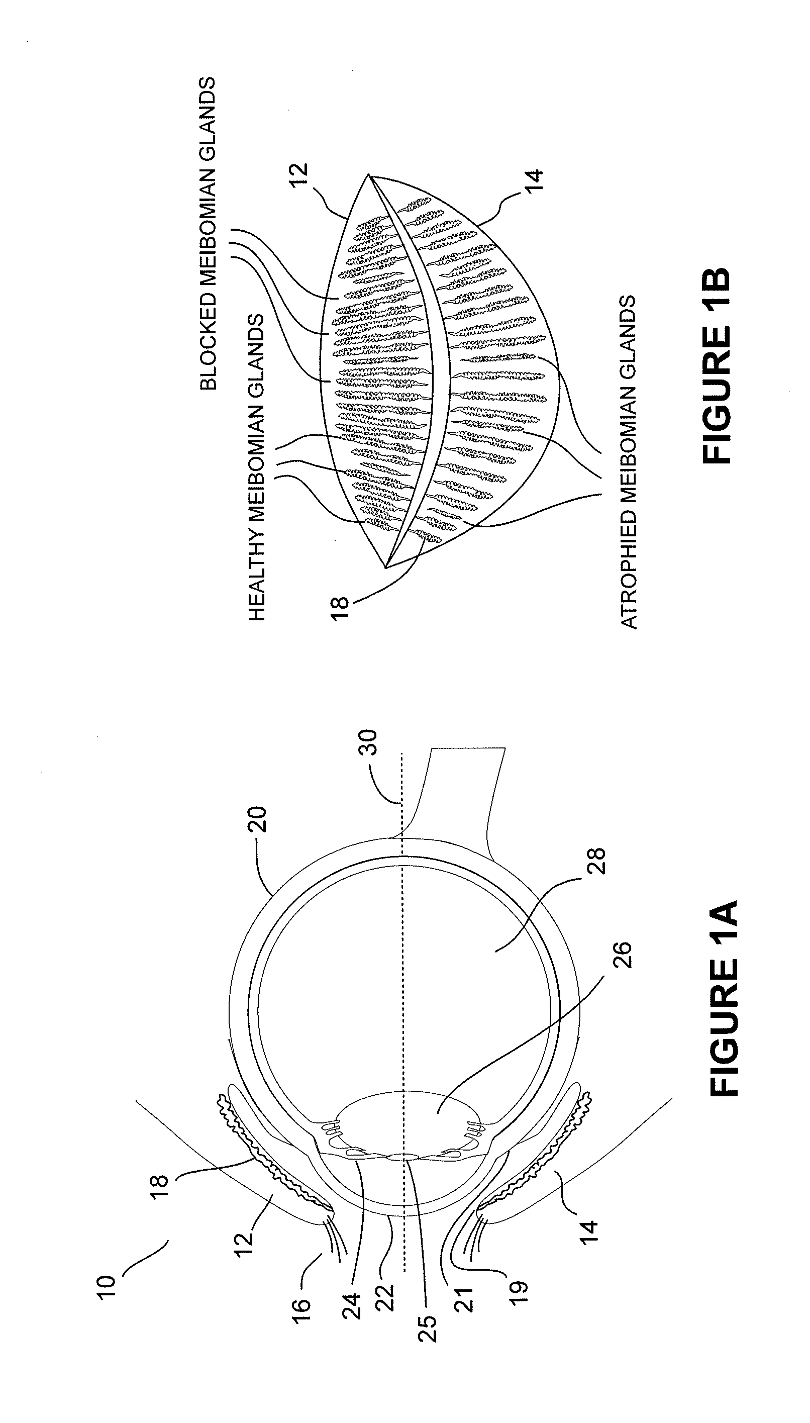
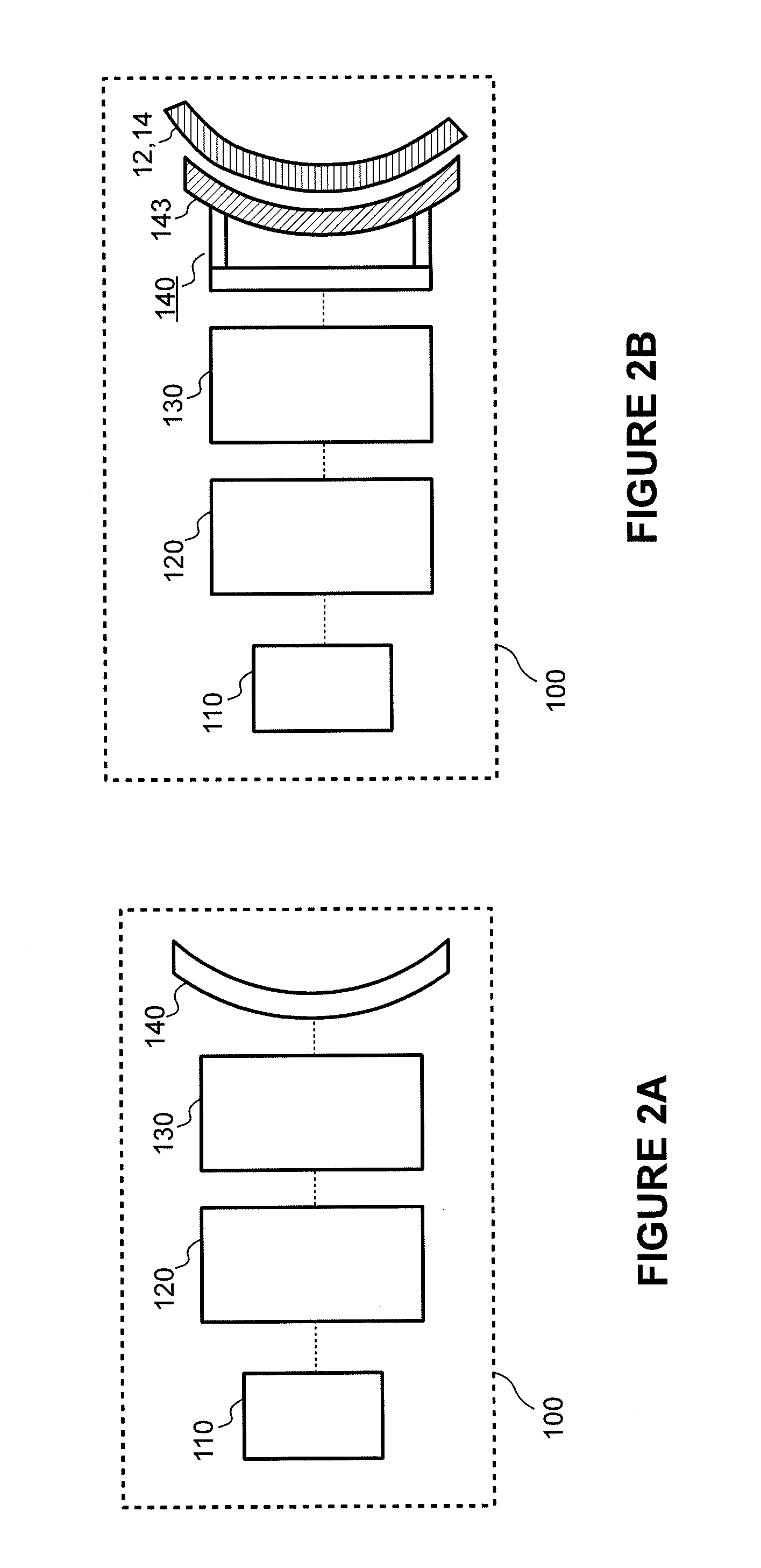
[0073]In the following detailed description, reference is made to the accompanying drawings, which form a part of the present disclosure. In the drawings, similar symbols typically identify similar components, unless context dictates otherwise. The illustrative embodiments described in the detailed description, drawings, and claims are not meant to be limiting. Other embodiments may be utilized, and other changes may be made, without departing from the spirit or scope of the subject matter presented herein. It will be readily understood that the aspects of the present disclosure, as generally described herein, and illustrated in the Figures, can be arranged, substituted, combined, and designed in a wide variety of different configurations, all of which are explicitly contemplated and form part of this disclosure.

[0074]The terminology used herein is for the purpose of describing particular embodiments only and is not intended to be limiting of the disclosure. It will be understood by...


PUM


Abstract

Systems, methods, and devices used to treat eyelids, meibomian glands, ducts, and surrounding tissue are described herein. In some embodiments, an eye treatment device is disclosed, which includes a scleral shield positionable proximate an inner surface of an eyelid, the scleral shield being made of, or coated with, an energy-absorbing material activated by a light energy, and an energy transducer positionable outside of the eyelid, the energy transducer configured to provide light energy at one or more wavelengths, including a first wavelength selected to heat the energy-absorbing material. Wherein, when the eyelid is positioned between the energy transducer and the scleral shield, the light energy from the energy transducer and the heated energy-absorbing material of the scleral shield conductively heats a target tissue region sufficiently to melt meibum within meibomian glands located within or adjacent to the target tissue region.

Description

CROSS-REFERENCE TO RELATED APPLICATIONS[0001]This application claims the benefit of U.S. Provisional Application No. 61 / 817,757, filed Apr. 30, 2013, which is incorporated herein by reference. Priority of the aforementioned filing date is claimed.BACKGROUND[0002]1. Field of the Invention[0003]The present disclosure relates to medical devices and methods of using the same. More particularly, the disclosure relates to systems, methods, and apparatus used to diagnose and treat conditions of the eye such as meibomian gland dysfunction and blepharitis, typically involving eyelids, meibomian glands, ducts, orifices, and surrounding tissue.[0004]2. Description of the Related Art[0005]Meibomian gland dysfunction (MGD) is thought to be the most common cause of evaporative dry eye disease, with studies showing a prevalence ranging from 20% to 60% in the general population. MGD is associated with a failure of meibomian glands to produce an adequate quantity of normal secretions (called meibum)...

Claims


Application Information

Patent Timeline
IPC IPC(8): A61F9/007A61F9/008A61F9/009
CPCA61F9/009A61F2009/00861A61F9/00802A61F9/0079A61B2017/00084A61F7/00A61F9/00718A61F9/008A61F2007/0002A61F2007/0088A61H5/00A61H23/02A61H23/0245A61H2201/0176A61H2201/0207A61H2201/0214A61H2201/0242A61H2201/025A61H2201/0257A61H2201/0285A61H2201/10A61H2201/501A61H2201/5028A61H2201/5043A61H2201/5061A61H2201/5082A61H2201/5092A61H2201/5097A61H2230/505A61N5/0624A61N5/0625A61N7/00A61N7/02A61N2005/0626A61N2005/0643A61N2005/0663
Inventor KELLEHER, BRIAN S.GAMBHIR, KABIR
Owner ALCON INC
Why Eureka
Try Eureka