
Circuit board capable of indicating the temperature of hot elements thereon

a technology of circuit boards and hot elements, applied in the direction of circuit inspection/indentification, instruments, material electrochemical variables, etc., can solve the problems of users getting easily burned, computers now consuming more and more power, and likely getting burned, so as to reduce the possibility of failure caused by overheated elements

Inactive Publication Date: 2006-09-28
ASUSTEK COMPUTER INC
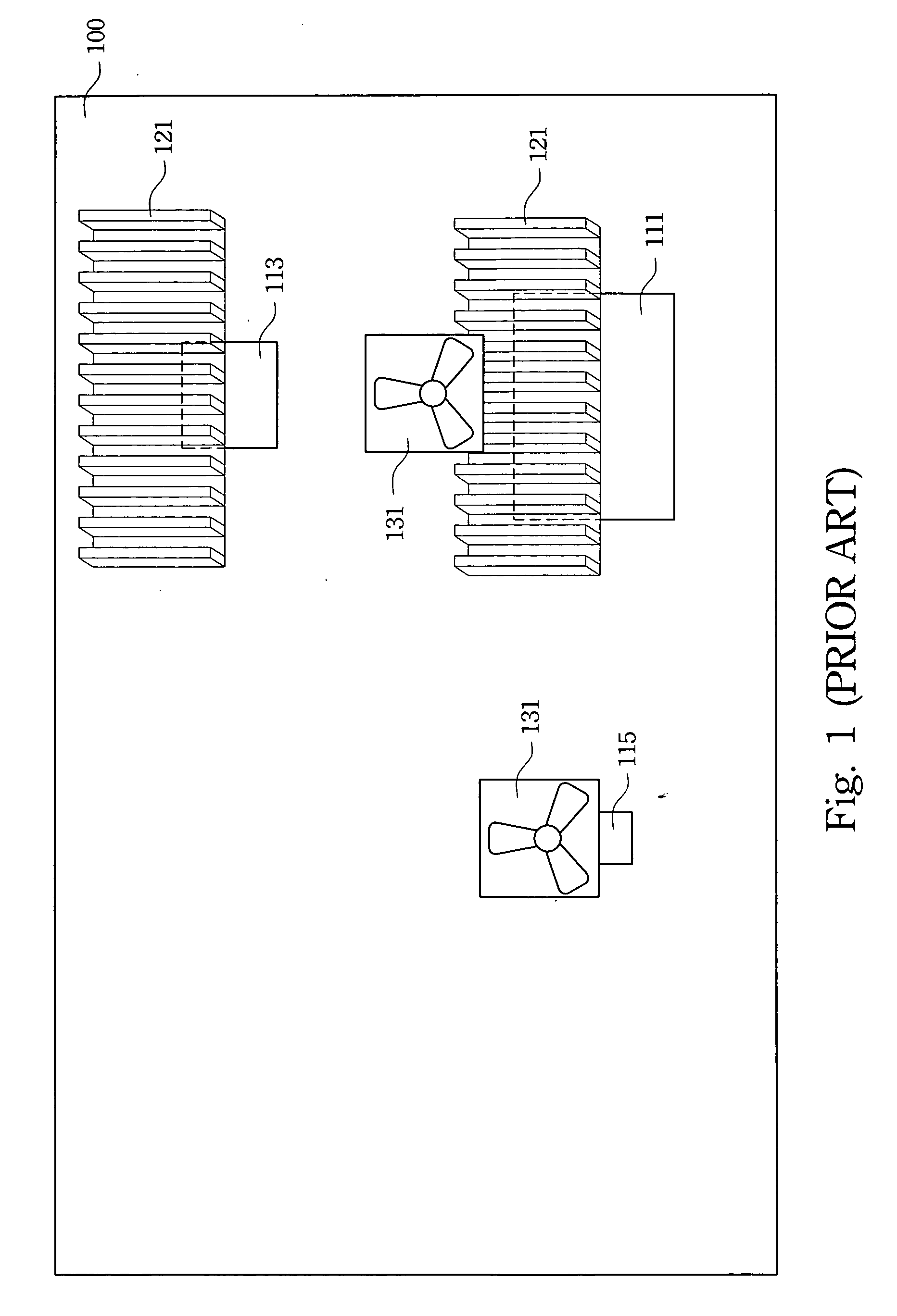
View PDF11 Cites 10 Cited by
  • Summary
  • Abstract
  • Description
  • Claims
  • Application Information

AI Technical Summary

Benefits of technology

[0011] Another aspect of the present invention provides a circuit board capable of indicating the temperature of the hot elements thereon, so that the failure of too-hot elements can be avoided as much as possible.
[0012] Still another aspect of the present invention provides a circuit board capable of indicating the temperature of the hot elements thereon, so that careless users are less likely to be burned by the hot elements.
[0020] Besides, according to the circuit board of the present invention capable of indicating the temperature of the hot elements thereon, the possibility of failure caused by overheated elements can be lowered.
[0021] Additionally, with the help of the circuit board of the present invention capable of indicating the temperature of the hot elements thereon, careless users are less likely to be burned by the hot elements.

Problems solved by technology

With the growth of processing speed and increase of functions, computers are now consuming more and more power, which makes the essential parts, i.e. the circuit boards, in the computers undertake more and more power conversion and generate more and more heat to be dissipated.
If users want to examine the elements on the circuit board, they could likely get burned because they have no means for determining temperatures thereof.
Consequently, in addition to the effort to further improve the efficiency for dissipating heat in order to avoid the hot elements such as CPU or chip sets on the circuit board being too hot, all manufactures are eventually required to face the problems that overheated elements frequently fail and make users get burned easily.
This brings forth another problem, i.e. the surface temperature of a heat-dissipating element cannot be readily determined by naked eyes.
Even so, unless (1) the heat-generating elements on the circuit boards are equipped with hardware circuits, (2) BIOS or DOS functions normally, and (3) monitors are available for displaying the result, such a hardware monitor program is completely useless.

Method used


Image

  • Circuit board capable of indicating the temperature of hot elements thereon
  • Circuit board capable of indicating the temperature of hot elements thereon
  • Circuit board capable of indicating the temperature of hot elements thereon

Examples


Embodiment Construction

[0028] Reference will now be made in detail to the present preferred embodiments of the invention, examples of which are illustrated in the accompanying drawings. Wherever possible, similar reference numbers are used in the drawings and the description to refer to the same or like parts.

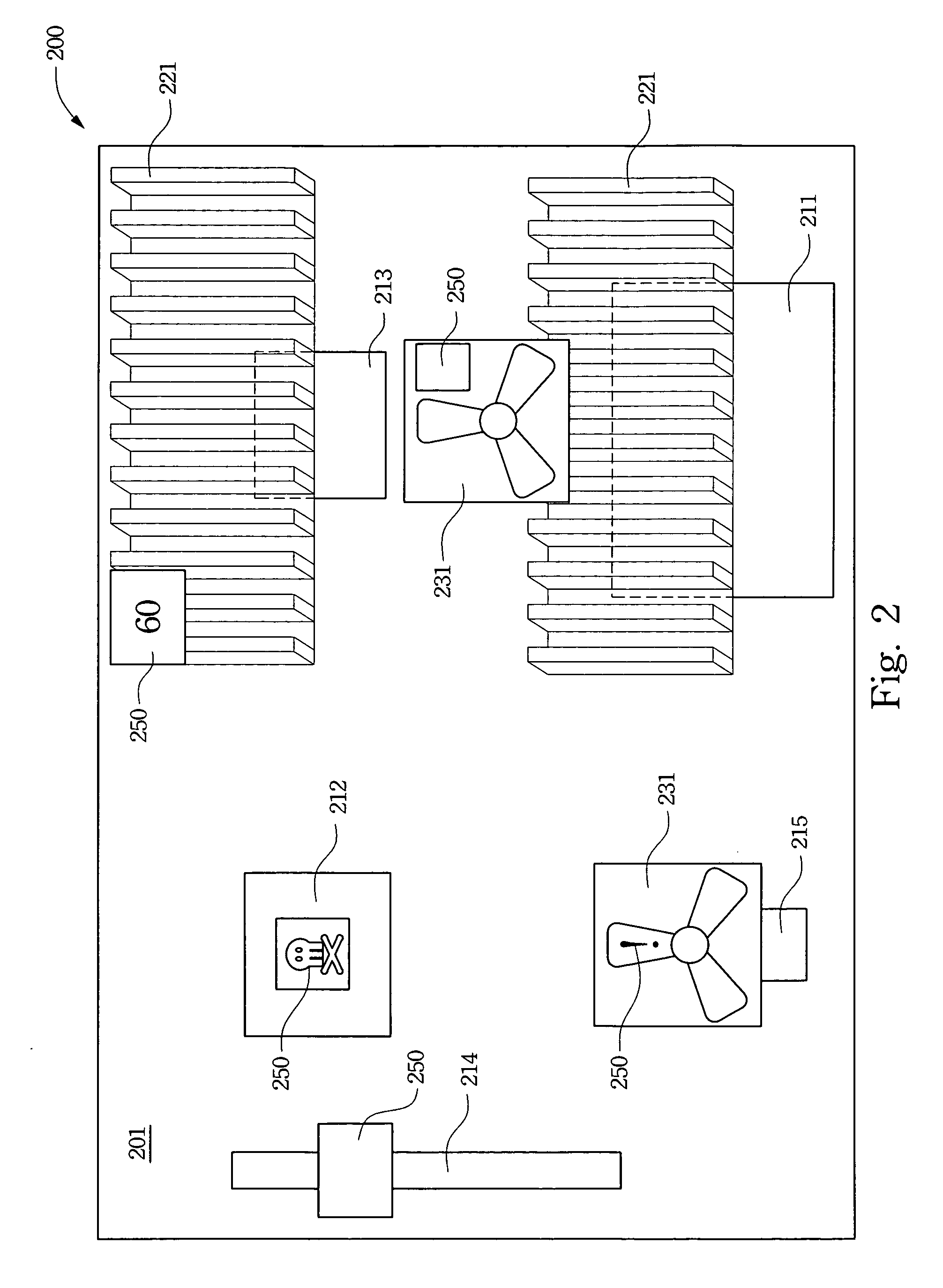
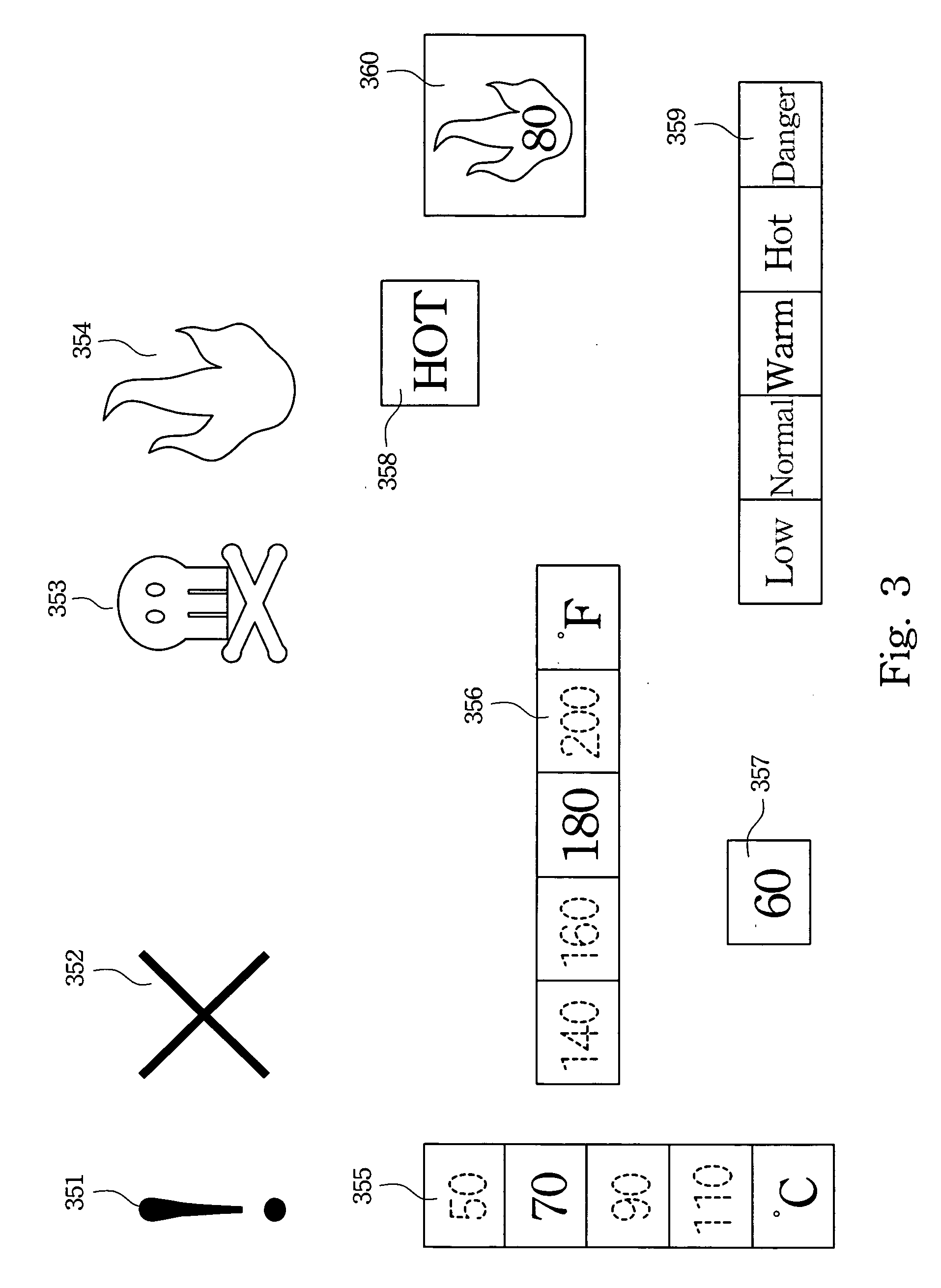
[0029] Reference is made to FIG. 2, illustrating a preferred embodiment of the circuit board of the present invention. The circuit board 200 for use in computers may include substrate 201, heat-generating elements 211, 212, 213, 214, and 215 assembled on substrate 201, and thermochromic material 250. The thermochromic material 250 at least partially covers the heat-generating elements, and changes color above a pre-determined temperature, instantly or gradually, to indicate a temperature condition of the heat-generating elements 211, 212, 213, 214 and 215.

[0030] The above-mentioned heat-generating elements are elements which can generate heat, such as, but not limited to, CPU 211, chip set 212 (sou...


PUM


Abstract

A circuit board capable of indicating the temperature of hot elements thereon is disclosed. The circuit board includes a substrate, a hot element and a thermochromic material. The hot element may be a chip set or a CPU. The thermochromic material may be inorganic thermochromic materials, or organic thermochromic materials, such as polymers, liquid crystals, dyes, or combinations thereof.

Description

RELATED APPLICATIONS [0001] The present application is based on, and claims priority from, Taiwan Application Serial Number 94109442, filed Mar. 25, 2005, the disclosure of which is hereby incorporated by reference herein in its entirety. BACKGROUND [0002] 1. Field of Invention [0003] The present invention relates to circuit boards. More particularly, the present invention relates to circuit boards capable of indicating the temperature of hot elements thereon. [0004] 2. Description of Related Art [0005] With the growth of processing speed and increase of functions, computers are now consuming more and more power, which makes the essential parts, i.e. the circuit boards, in the computers undertake more and more power conversion and generate more and more heat to be dissipated. If users want to examine the elements on the circuit board, they could likely get burned because they have no means for determining temperatures thereof. Consequently, in addition to the effort to further impro...

Claims


Application Information

Patent Timeline
IPC IPC(8): G01N27/28
CPCH05K1/0201H05K1/0269H05K2201/10151H05K2203/161
Inventor CHOU, HUNG-HSIANGCHANG, CHUAN-TECHEN, CHING-CHUNG
Owner ASUSTEK COMPUTER INC
Learn More