
Ink jet printer and preliminary-ejection control method

a technology of ejection control and printer, which is applied in the direction of printing, other printing apparatus, etc., can solve the problems of ejection failure, complex control, and inconvenient pre-ejection method for continuous paper without margin, so as to reduce the time at least by half, and reduce the number of counters

Inactive Publication Date: 2006-09-28
COPYER
View PDF8 Cites 16 Cited by
  • Summary
  • Abstract
  • Description
  • Claims
  • Application Information

AI Technical Summary

Benefits of technology

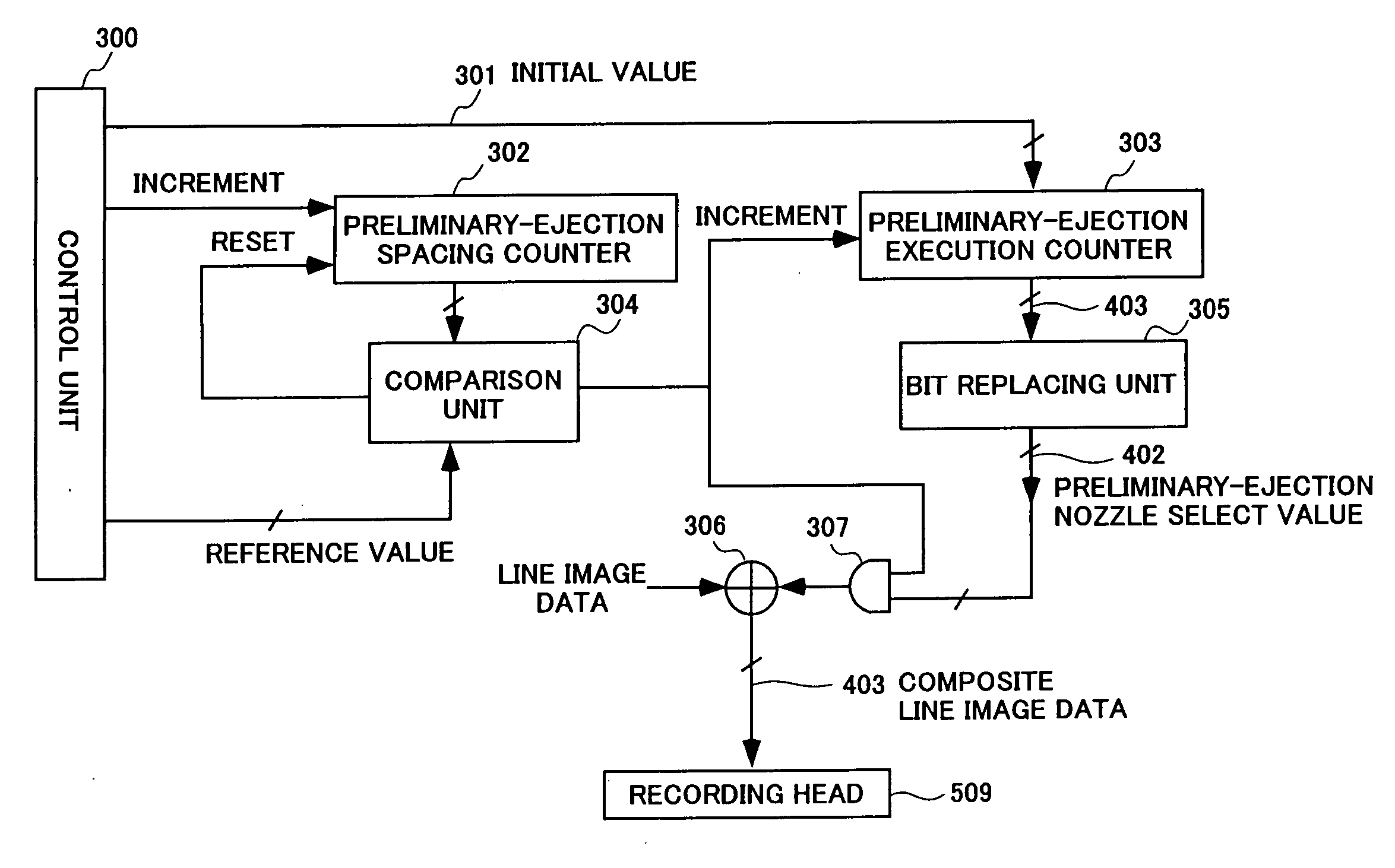
[0016] The preliminary-ejection means exchanges the bit positions in such a way that high-order bits and low-order bits of the preliminary-ejection execution counter are replaced with reach other. Thus, the selection sequence of the nozzles, from which ink is preliminary-ejected, can be very easily distributed pseudo randomly.
[0018] The preliminary-ejection means comprises a preliminary-ejection spacing counter, provided for common use by all nozzles, for counting a number of recorded lines and, each time a predetermined number of lines are counted, updates the preliminary-ejection execution counter to indicate a time at which preliminary-ejection is to be performed. This configuration reduces the number of counters required.
[0019] The preliminary-ejection means changes the predetermined number of lines according to a print speed. Changing the predetermined number of line in this way prevents one round or time, required for preliminary-ejecting from all nozzles, from becoming extremely long due to a change in the print speed.
[0020] It is also possible that the preliminary-ejection execution counter is provided for common use by x partial nozzle groups, nozzles from which ink is preliminary-ejected are determined for all partial nozzle groups based on the value of the preliminary-ejection execution counter, and preliminary ejection is performed for each partial nozzle group, wherein the x partial nozzle groups are generated by dividing a total number of nozzles, N, of one recording head by x (x is an integer equal to or larger than 2). Dividing the total number of nozzles, N, of one recording head by x can reduce the number of bits required for the preliminary-ejection execution counter. In addition, performing preliminary ejection for each partial nozzle group will reduce the one round of time required for preliminary-ejecting ink from all nozzles (reduces the time at least by half).

Problems solved by technology

Hei 3-45814 and Japanese Patent Laid-Open Publication No. 2002-225301, which ejects ink in the margin or the paper fastening part of a recording paper, does not interrupt the print operation; however, this preliminary-ejection method is not suitable for continuous paper that has no margin or paper that has a long recording size.
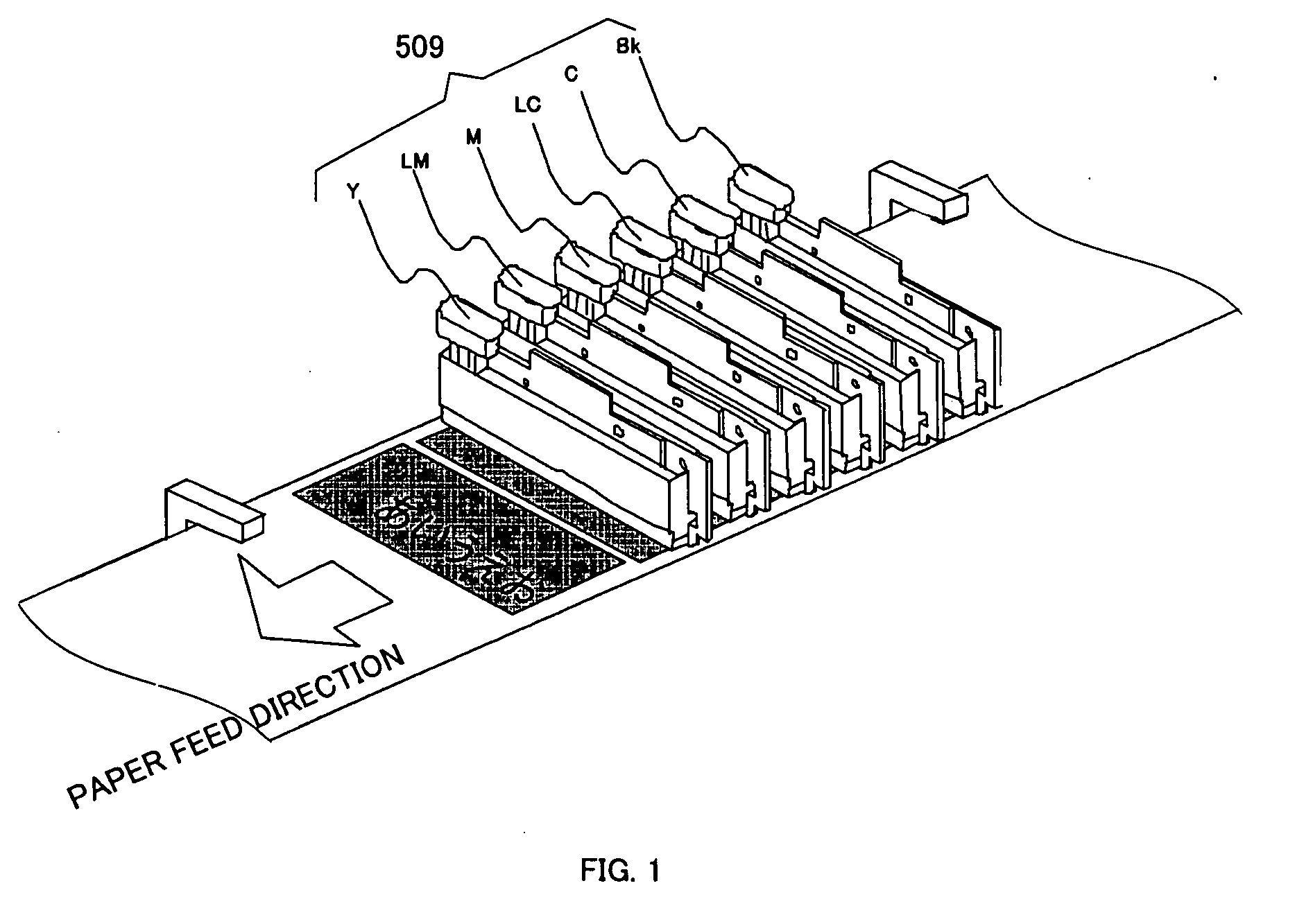
In particular, on a conventional ink jet printer that uses a long-type line head on which plural nozzles are arranged linearly across the full width of recording paper, the print operation is usually executed continuously for a relatively long time to continuously print on a continuous paper such as roll paper.
In this case, the viscosity of the ink of a nozzle, from which ink is not ejected for a predetermined period, is increased with the result that the high-viscosity ink sometimes causes an ejection failure.
That is, this method requires time measuring means (for example, counters), one for each nozzle, and makes the control complex especially on a line head with a large number of nozzles.
However, the preliminary ejection that is performed for all nozzles at the same time or regularly involves the following problems.
That is, though a recent recording head is extremely miniaturized and one printed droplet becomes so small that it is difficult to be visually recognized, there is a possibility that, when data ejected on paper is arranged in a line, the user can visually recognize the preliminary-ejected image pattern and therefore the recording quality is degraded.

Method used


Image

  • Ink jet printer and preliminary-ejection control method
  • Ink jet printer and preliminary-ejection control method
  • Ink jet printer and preliminary-ejection control method

Examples


Embodiment Construction

[0001] 1. Field of the Invention

[0002] The present invention relates to an ink jet printer that performs a so-called preliminary ejection for recovering the recording heads and the preliminary-ejection control method thereof.

[0003] 2. Related Art

[0004] Conventionally, an operation called “preliminary ejection” has been performed on a printer, such as an ink jet printer, because ink is not always ejected from all the nozzles during the execution of recording. The “preliminary ejection” refers to the ejection of ink from the nozzles of the recording heads at a predetermined time, not to record image data, but to always keep the nozzles supplied with fresh ink even if those nozzle are not used for image data recording. This preliminary-ejection processing removes the causes of ink ejection failures, such as bubbles, dust, or high-viscosity ink thicken by the vaporization of solvent to such an extent that the viscosity is too high for the ink to be used recording and, in addition, ad...


PUM


Abstract

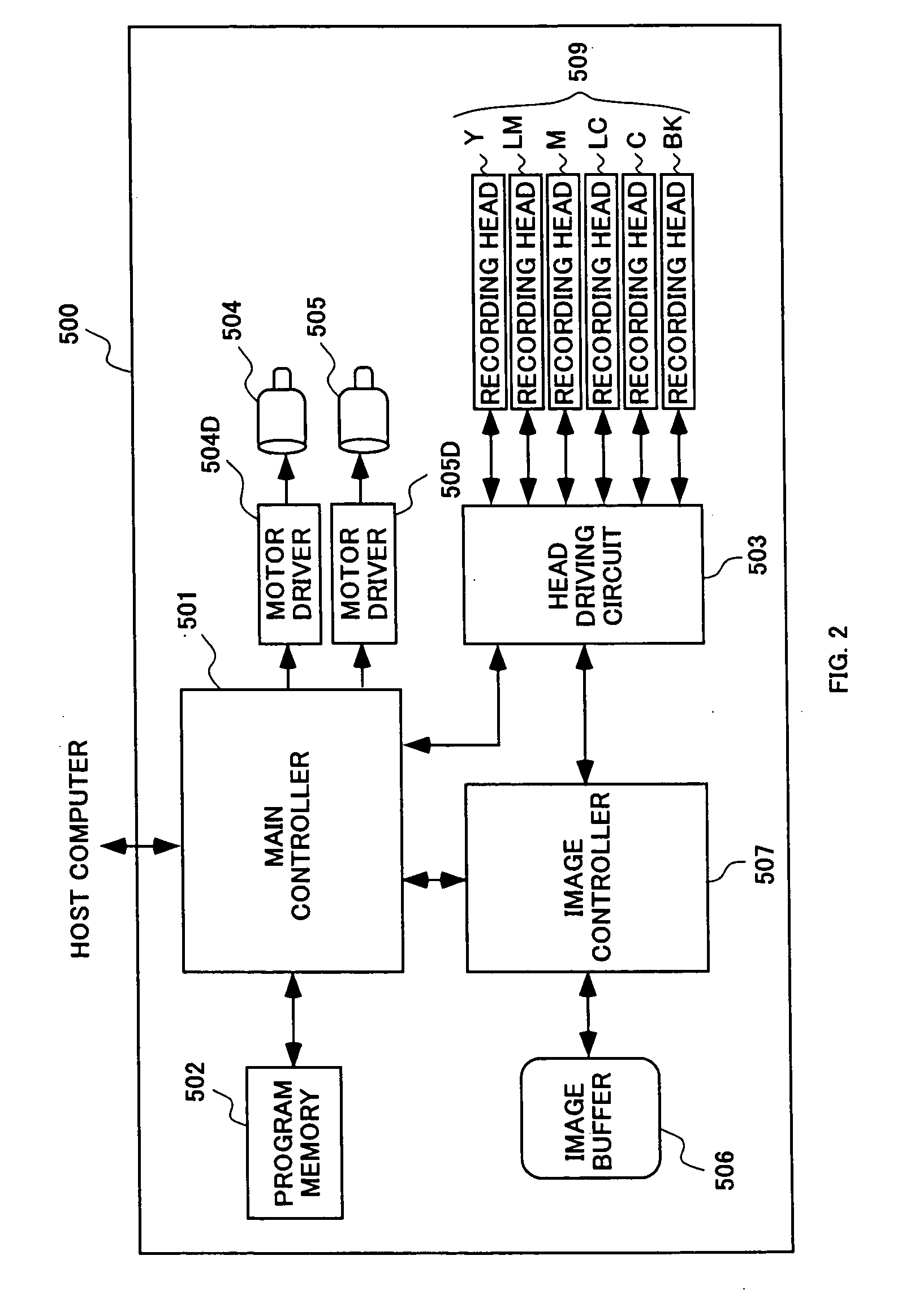
The present invention makes it possible to continuously print for a long time with no print interruption and provides simple control for making a preliminary-ejected image pattern difficult to be visually recognized when paper preliminary-ejecting is performed on a printer that uses recording heads each having plural linearly-arranged ink-ejecting nozzles. To do so, a preliminary-ejection execution counter 303 is provided for counting the number of preliminary-ejection executions to determine nozzles, from which ink is ejected at each preliminary-ejection time, when ink is periodically ejected onto a recording medium from one or more nozzles at a time in a preliminary manner at a predetermined time during the image data recording operation through recording heads 509. The nozzles from which ink is ejected are determined based on a preliminary-ejection nozzle select value generated by exchanging the bit positions of the count value of the preliminary-ejection execution counter.

Description

DETAILED DESCRIPTION [0001] 1. Field of the Invention [0002] The present invention relates to an ink jet printer that performs a so-called preliminary ejection for recovering the recording heads and the preliminary-ejection control method thereof. [0003] 2. Related Art [0004] Conventionally, an operation called “preliminary ejection” has been performed on a printer, such as an ink jet printer, because ink is not always ejected from all the nozzles during the execution of recording. The “preliminary ejection” refers to the ejection of ink from the nozzles of the recording heads at a predetermined time, not to record image data, but to always keep the nozzles supplied with fresh ink even if those nozzle are not used for image data recording. This preliminary-ejection processing removes the causes of ink ejection failures, such as bubbles, dust, or high-viscosity ink thicken by the vaporization of solvent to such an extent that the viscosity is too high for the ink to be used recording...

Claims


Application Information

Patent Timeline
Patent Type & Authority Applications(United States)
IPC IPC(8): B41J29/38
CPCB41J2/16526
Inventor NAKAHARA, YASUNORI
Owner COPYER
Learn More