Method for cleaning liquid ejection apparatus and liquid ejection apparatus

a technology of liquid ejection and cleaning liquid, which is applied in the direction of printing, other printing apparatus, etc., can solve the problems of printing failure, dust may clog the nozzle, and produce bubbles in the nozzle, so as to save costs and prevent the enlargement of the waste tank

Inactive Publication Date: 2006-09-28
SEIKO EPSON CORP
View PDF5 Cites 27 Cited by
  • Summary
  • Abstract
  • Description
  • Claims
  • Application Information

AI Technical Summary

Benefits of technology

[0011] Accordingly, it is an objective of the present invention to provide a method for cleaning a liquid e

Problems solved by technology

Also, in this state, dust may clog the nozzles.
Further, air may enter the nozzles through the openings of the nozzles and thus produce bubbles in the nozzles.
This may cause a printing failure such as missing dots.
However, a flow of the ink caused by such cleaning may contain usable ink, which is discarded together with the unusable ink.
However, the pigment ink contains pigment particles that are dispersed in ink solvent, which increases volatility of the ink compared to the dye ink.
This may cause a problem such as a blockage of

Method used


Image

  • Method for cleaning liquid ejection apparatus and liquid ejection apparatus
  • Method for cleaning liquid ejection apparatus and liquid ejection apparatus
  • Method for cleaning liquid ejection apparatus and liquid ejection apparatus

Examples


first embodiment

[0030] the present invention will now be described with reference to FIGS. 1 to 8.

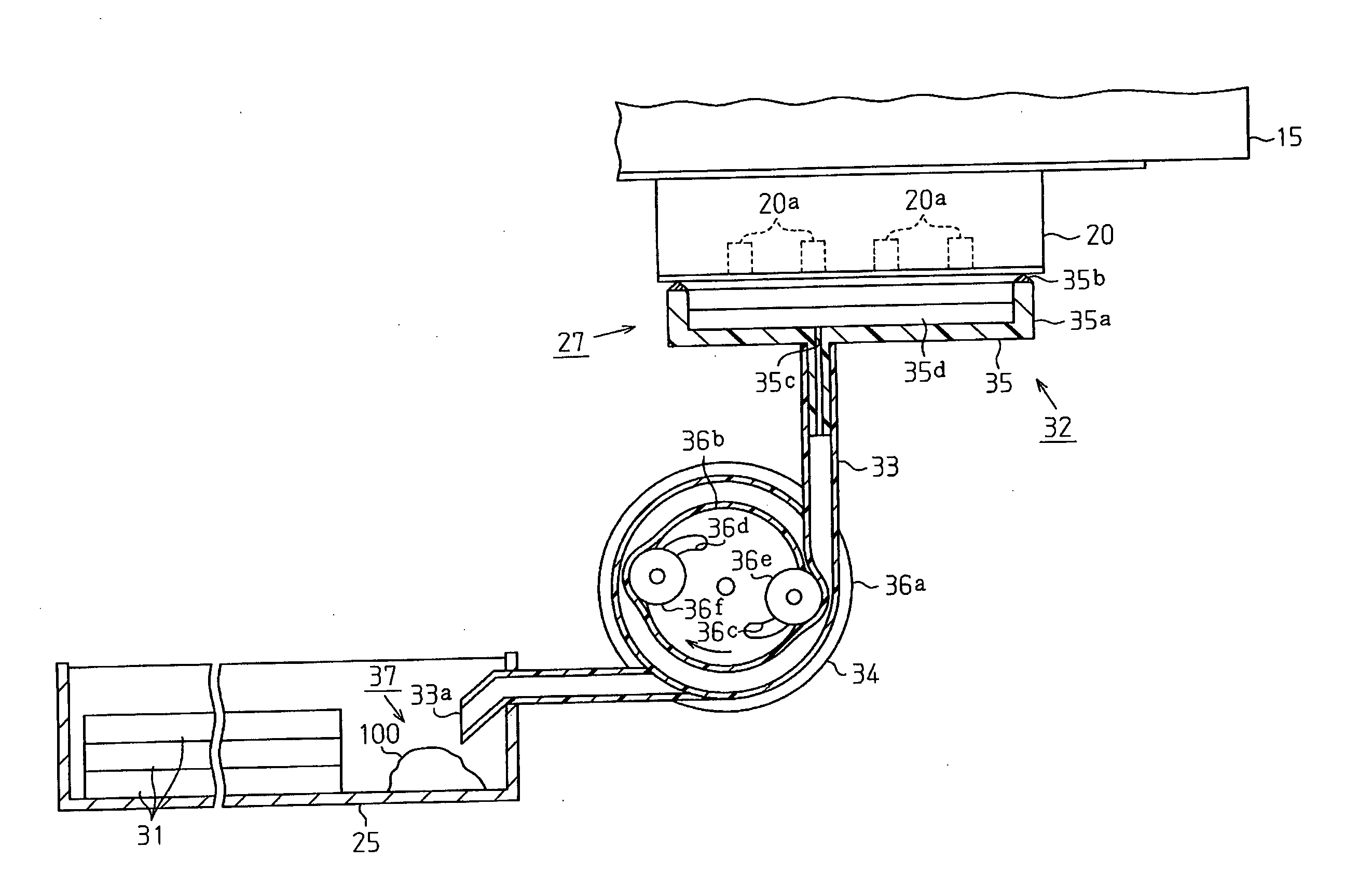
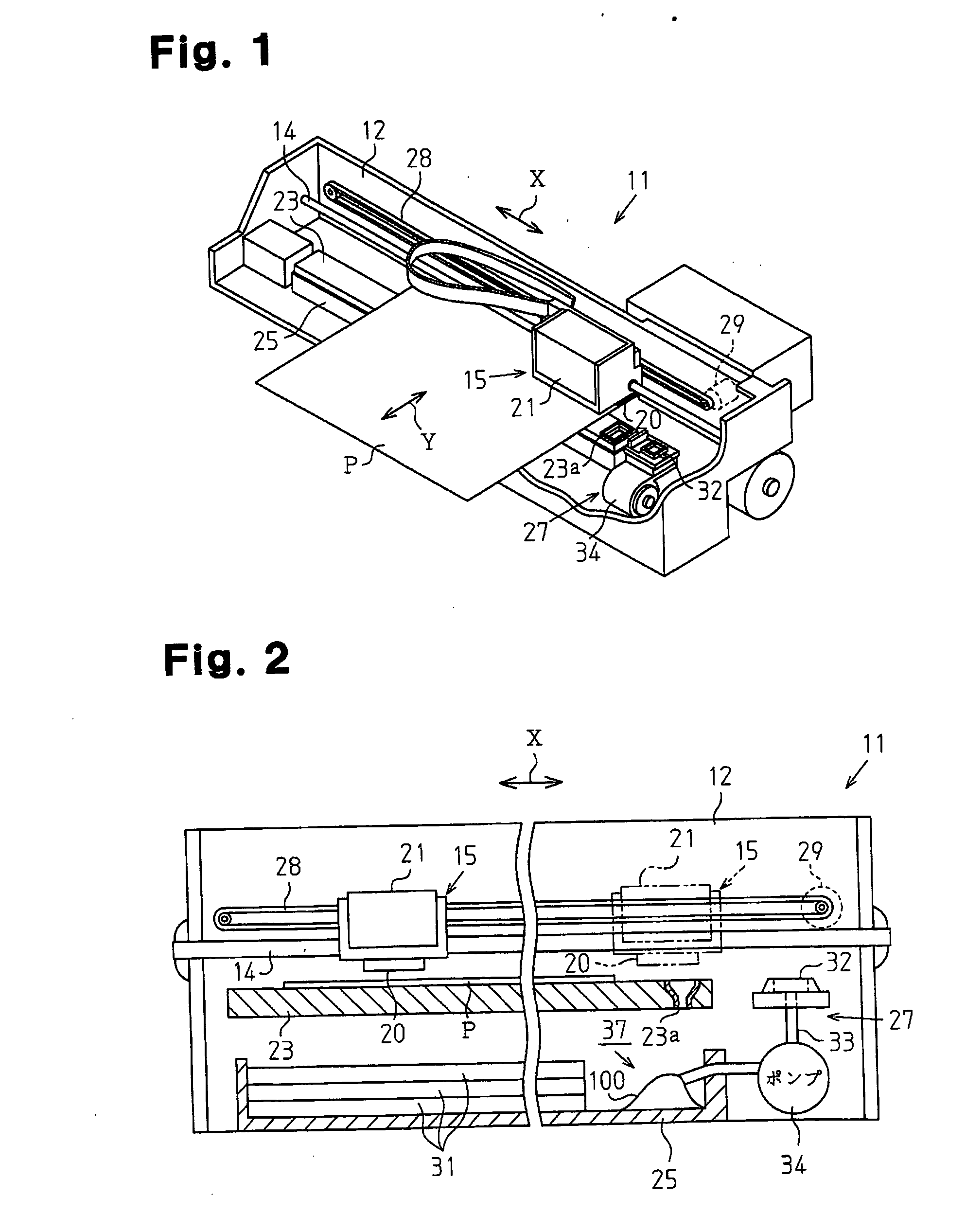
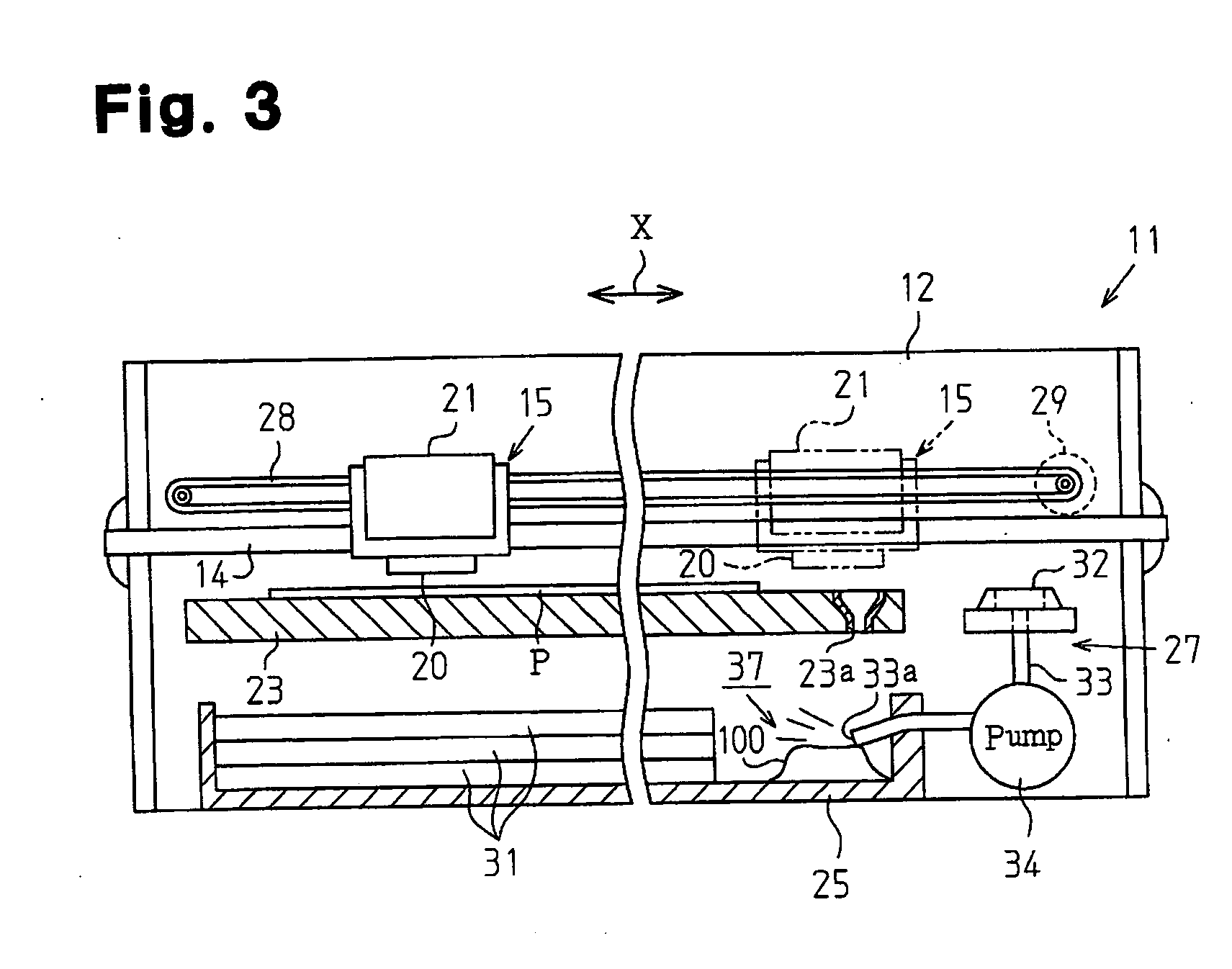
[0031] As shown in FIGS. 1 and 2, a printer 11, which is a liquid ejection apparatus according to the first embodiment, includes a frame 12, a guide member 14, a carriage 15, a recording head20 serving as a liquid ejection head, an ink cartridge 21, a platen 23, a waste tank 25, and a head cleaning mechanism 27.

[0032] The frame 12 accommodates the printer 11 as a whole. The guide member 14 is supported by the frame 12 in a suspended state and extends in the longitudinal direction of the frame 12. The guide member 14 is passed through the carriage 15 in such a manner that the carriage 15 is movable along the guide member 14. The carriage 15 is connected to a carriage motor 29 through a timing belt 28. The carriage 15 is thus reciprocated along the guide member 14, or in a main scanning direction X, through operation of the carriage motor 29.

[0033] The recording head 20 is formed in a lower portion of ...


PUM


Abstract

A printer includes a recording head having a nozzle through which ink is ejected onto a paper sheet and a waste tank in which the ink is retained as waste liquid after having been drained from the recording head. A deposit of the waste liquid is formed in the waste tank. The printer has a suction pump used for forcibly drawing and draining the ink from the nozzle. The suction pump functions also as a gas blasting device that blasts gas to the deposit in the waste tank for blowing off the deposit. This suppresses the amount of the ink consumed in maintenance of the printer.

Description

CROSS-REFERENCE TO RELATED APPLICATIONS [0001] This application is based upon and claims the benefit of priority from prior Japanese Patent Applications No. 2005-077491 filed on Mar. 17, 2005, No. 2005-326447 filed on Nov. 10, 2005, No. 2006-031571 filed on Feb. 8, 2006, the entire contents of which are incorporated herein by reference. BACKGROUND OF THE INVENTION [0002] The present invention relates to methods for cleaning liquid ejection apparatuses that eject liquid droplets through a liquid ejection head, including inkjet recording apparatuses, display manufacturing apparatuses, electrode manufacturing apparatuses, and biochip manufacturing apparatuses, and such liquid ejection apparatuses. [0003] As a typical liquid ejection apparatus that ejects liquid onto a target, an inkjet printer is known. The inkjet printer ejects ink droplets onto a sheet of paper and thus prints an image on the paper sheet. The printer includes a plurality of nozzles that are defined in a recording hea...

Claims


Application Information

Patent Timeline
IPC IPC(8): B41J2/165
CPCB41J2/16523B41J2/16552B41J2/1714B41J2/1721B41J2/17596B41J2/185B41J29/17
Inventor FUKASAWA, SHIGENORIHAYAKAWA, HITOSHI
Owner SEIKO EPSON CORP
Why Eureka
Try Eureka