Apparatus and method for tracking sampling clock in multi-carrier communication system

a communication system and multi-carrier technology, applied in multi-frequency code systems, digital transmission, amplitude demodulation, etc., can solve the problem that the conventional receiver requires a large amount of resources, and achieve the effect of reducing the complexity of the receiver and reducing the load of the computing uni

Active Publication Date: 2006-09-28
REALTEK SEMICON CORP
View PDF5 Cites 6 Cited by
  • Summary
  • Abstract
  • Description
  • Claims
  • Application Information

AI Technical Summary

Benefits of technology

[0013] A further objective of the claimed invention is to provide an apparatus and me...

Problems solved by technology

By equation (1), it is known that the conventional receiver requires the consumption of a great a...

Method used


Image

  • Apparatus and method for tracking sampling clock in multi-carrier communication system
  • Apparatus and method for tracking sampling clock in multi-carrier communication system
  • Apparatus and method for tracking sampling clock in multi-carrier communication system

Examples


Embodiment Construction

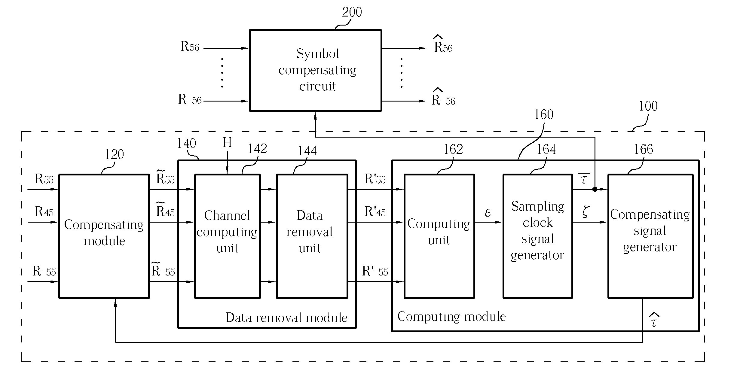
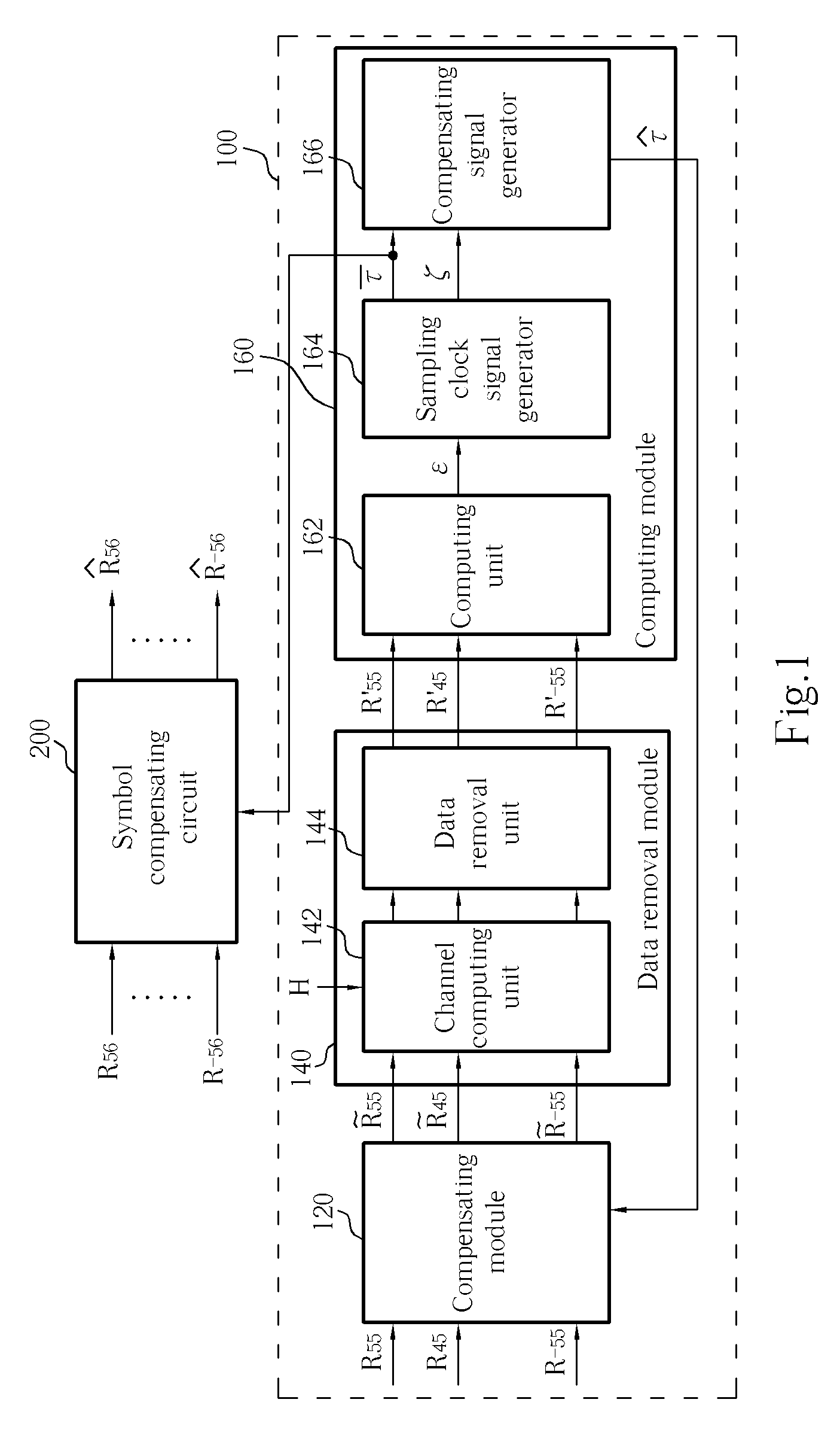
[0019] Please refer to FIG. 1. FIG. 1 is a block diagram of an apparatus 100 according to the present invention. In the present embodiment, the apparatus 100 generates a sampling clock signal according to a plurality of received symbols R55, R45, . . . , R−55 corresponding to a plurality of pilot symbols and transmitting the sampling clock signal into a symbol compensating circuit 200, in order to control the symbol compensating circuit 200 to compensate all received symbols R56, . . . , R−56. These received symbols include data symbols and pilot symbols. Therefore, all the received symbol R56, . . . , R−56 will not be influenced by the sampling clock offsets.

[0020] In an embodiment, the apparatus 100 comprises a compensating module 120, a data removal module 140, and a computing module 160. The compensating module 120 generates a compensated symbol by adjusting a received symbol R corresponding to each pilot symbol according to a compensating signal Please refer to the followi...


PUM


Abstract

An apparatus and method for tracking a sampling clock are disclosed. The apparatus includes a compensating unit compensating phases of a first and a second received symbols according to a compensating signal and thereby generating a first and a second compensated symbols; a data removal module removing a first predetermined transmitted data from the first compensated symbol, and a second predetermined transmitted data from the second compensated symbol and thereby generating a first and a second data removal symbols; and a computing module generating a sampling clock offset according to the first and the second data removal symbols, and adjusting the sampling clock signal according to the sampling clock offset.

Description

BACKGROUND OF THE INVENTION [0001] 1. Field of the Invention [0002] The present invention relates to a multi-carrier communication system, and more specifically, to an apparatus for tracking a sampling clock of a multi-carrier communication system. [0003] 2. Description of the Prior Art [0004] A transmitter of a multi-carrier communication system utilizes a plurality of sub-carriers to modulate predetermined transmitted data and transmits the modulated data to a receiver in the form of a continuous data flow. At this time, the receiver samples the above-mentioned continuous data flow utilizing a sampling clock. When the frequency of the sampling clock includes a small offset, a phase-shift may be occurred between the received symbol generated by the receiver and the original transmitted data transmitted by the transmitter. Therefore, the multi-carrier communication system compensates the above-mentioned N received symbols by estimating a sampling clock offset utilizing a plurality o...

Claims


Application Information

Patent Timeline
IPC IPC(8): H04K1/10
CPCH04L27/2662H04L27/2675H04L27/2695
Inventor WU, KUO-MINGLIU, DER-ZHENG
Owner REALTEK SEMICON CORP
Why Eureka
Try Eureka