Method and device for wireless communication

a wireless communication and wireless communication technology, applied in the field of wireless communication system and uplink transmission, can solve the problems of inability to meet the requirements of the scenario, collision, and failure to receive and decode uplink transmission, so as to improve the capacity of the entire system, avoid ambiguity of uplink transmission between multiple uplink receiving nodes, and improve link performance

Active Publication Date: 2019-11-07
APEX BEAM TECH LLC
View PDF0 Cites 3 Cited by
  • Summary
  • Abstract
  • Description
  • Claims
  • Application Information

AI Technical Summary

Benefits of technology

[0169]Compared with the prior art, the present disclosure has the following technical advantages.
[0170]In the case of a preamble transmission collision, it is possible that the base station side can still correctly receive and decode the uplink data, thereby improving the capacity of the entire system.
[0171]The ambiguity of uplink transmission between multiple uplink receiving nodes is avoided, thereby improving link performance, reducing false alarm probability, and reducing receiver complexity.

Problems solved by technology

Especially for uplink transmission, in the scenario with high requirement for low latency or capacity, for example, Ultra Reliable Low Latency Communication (URLLC) has very strict delay requirements, Machine Type Communication (mMTC) or NB-IoT, or the application scenario of enhanced Machine Type Communication (eMTC) has high requirement for the system capacity, the grant-based approach cannot meet the requirements of the scenario due to the scheduling delay and the limitation of the overhead of the transmission-initiated overhead.
In the process of Grant-free uplink transmission, collision may occur due to lack of centralized dynamic scheduling and resource coordination.
If the associated Grant-free data transmission still collides, eventually it may result in the uplink transmission not being successfully received and decoded.
On the other hand, even if the Grant-free uplink transmission does not include the preamble transmission, when there are multiple receivers (such as multiple TRPs), it is likely that the uplink transmission may be received by a non-target receiver, resulting in link performance degradation or false alarms, or also increasing the complexity of the receiver.

Method used


Image

  • Method and device for wireless communication
  • Method and device for wireless communication
  • Method and device for wireless communication

Examples


embodiment 1

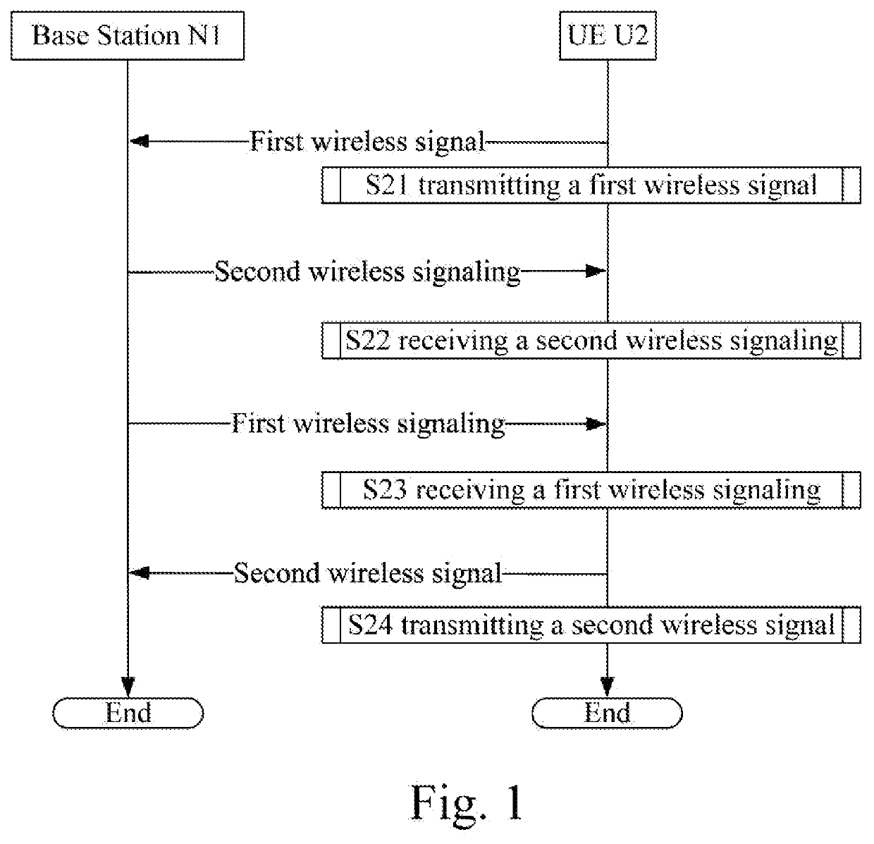
[0185]Embodiment 1 shows a wireless signal transmission flow diagram, as shown in FIG. 1. In FIG. 1, the base station N1 is a maintenance base station of the serving cell of the UE U2.

[0186]For the base station N1, the first wireless signal is received in Step S11, the second wireless signaling is transmitted in Step S12, the first wireless signaling is transmitted in Step S13, and the second wireless signal is received in Step S14.

[0187]For UE U2, the first wireless signal is transmitted in Step S21, the second wireless signaling is received in Step S22, the first wireless signaling is received in Step S23, and the second wireless signal is transmitted in Step S24.

[0188]In Embodiment 1, the first wireless signal is generated by a first sequence; the first wireless signal is used to determine a first time interval by the base station N1; the first time interval is a time interval between a first time instant and a second time instant; the first time instant is a starting time instan...

embodiment 2

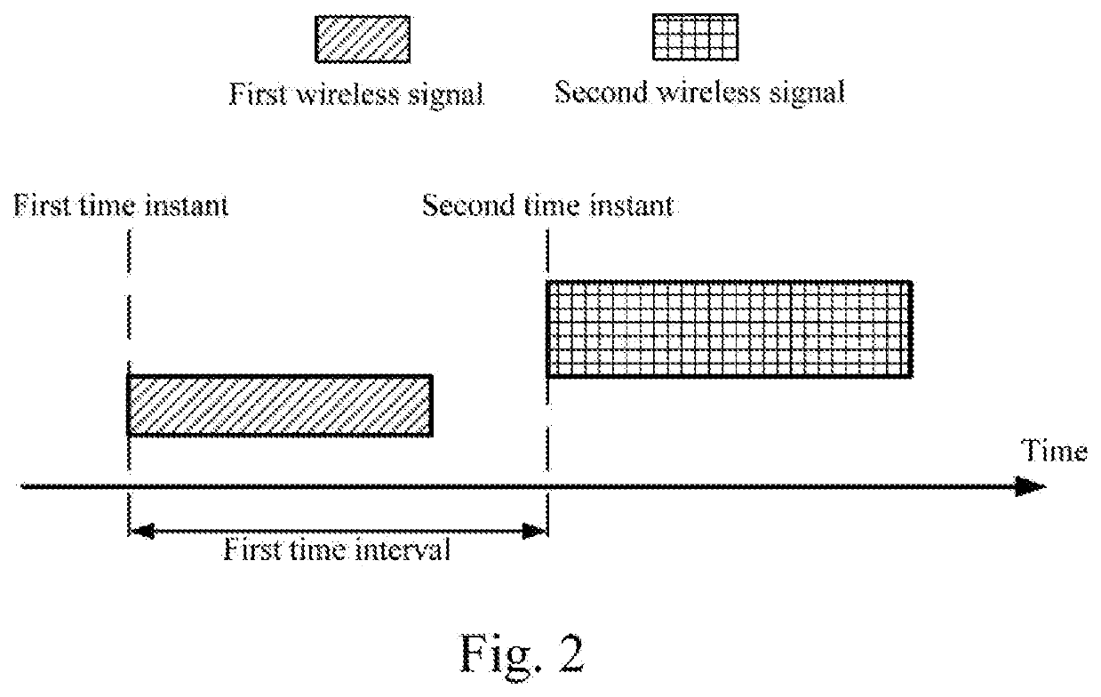
[0207]Embodiment 2 shows relationship between a first wireless signal and a second wireless signal, as shown in FIG. 2. In FIG. 2, the horizontal axis represents time, the rectangle filled by slashes represents the first wireless signal, and the rectangle filled by cross-lines represents the second wireless signal.

[0208]In Embodiment 2, the first wireless signal is generated by a first sequence; the first wireless signal is used to determine a first time interval; the first time interval is a time interval between a first time instant and a second time instant; the first time instant is a starting time instant at which a transmitter of the first wireless signal transmits the first wireless signal; the second time instant is a starting time instant at which a transmitter of the second wireless signal transmits the second wireless signal; the first time instant is earlier than the second time instant.

[0209]In one embodiment, the transmission channel corresponding to the first wireless...

embodiment 3

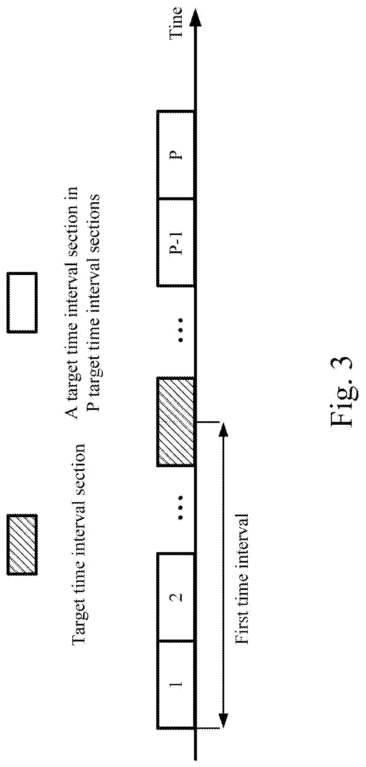
[0219]Embodiment 3 illustrates a relationship between the first time interval and the target time interval, as shown in FIG. 3. In FIG. 3, the horizontal axis represents time, the unfilled rectangle represents one time interval range in P time interval ranges, and the rectangle filled by slashes represents the target interval range.

[0220]In Embodiment 3, any two time interval ranges of the P time interval ranges do not overlap; the P is a positive integer. The first time interval belongs to a target time interval range; the target time interval range is a time interval range of the P time interval ranges.

[0221]In one embodiment, one time interval range refers to a continuous range of one time interval.

[0222]In one embodiment, the phrase that any two time interval ranges of the P time interval ranges do not overlap refers to no time interval belongs to two the time interval ranges.

[0223]In one embodiment, the interval lengths of any two time interval ranges of the P time interval ran...


PUM


Abstract

A user equipment transmits a first wireless signal and transmits a second wireless signal; the first wireless signal is generated by a first sequence; the first wireless signal is used to determine a first time interval; the first time interval is a time interval between a first and a second time instant; the first time instant is a starting time instant at which a transmitter of the first wireless signal transmits the first wireless signal; the second time instant is a starting time instant at which a transmitter of the second wireless signal transmits the second wireless signal; the first time instant is earlier than the second time instant; the second wireless signal occupies a first wireless resource; the first wireless resource is one of J candidate wireless resources; the first time interval is used to determine the first wireless resource out of the J candidate wireless resources.

Description

CROSS-REFERENCE TO RELATED APPLICATION[0001]This application is a continuation of International Application No. PCT / CN2017 / 072131, filed Jan. 22, 2017, the full disclosure of which is incorporated herein by reference.BACKGROUNDTechnical Field[0002]The present disclosure relates to a transmission scheme in a wireless communication system, and in particular to a method and device related to uplink transmission.Related Art[0003]The application scenarios of future wireless communication systems are increasingly diversified, and different application scenarios impose different performance requirements on the system. In order to meet the different performance requirements of various application scenarios, Wireless Access Network (RAN) #72 plenary meeting of the 3rd Generation Partner Project (3GPP) decided to conduct a search for the new air interface technology (New Wireless, NR).[0004]In existing cellular wireless communication systems (such as Long Term Evolution (LTE)), uplink and dow...

Claims


Application Information

Patent Timeline
Patent Type & Authority Applications(United States)
IPC IPC(8): H04L5/00H04W72/04H04W74/08H04W88/06H04W88/10
CPCH04W72/0493H04W72/0453H04L5/0082H04W74/0833H04W72/0446H04W88/10H04W88/06H04W72/02H04W72/53
Inventor ZHANG, XIAOBO
Owner APEX BEAM TECH LLC
Why Eureka
Try Eureka